This thread has been locked.

If you have a related question, please click the "Ask a related question" button in the top right corner. The newly created question will be automatically linked to this question.

MCT8316Z: Different parameters required for each direction of the motor

Part Number: MCT8316Z

Hello,

I am working with the MCT8316Z0R (24V on a custom PCB) and have found that different parameters are required for each direction in order to get good performance out of the BLDC motors we are using. Usually this just involves changing ADVANCE_LVL based on which direction the motor is spinning but sometimes different DLY_TARGETs make an impact as well. Changing these parameters based on the direction of the motor can sometimes result in 2-3x efficiency increases. Is this to be expected? We have tested on 5+ different BLDC motors and have found that the need for different parameters in the CW and CCW directions across the board.

Also if you could share any general advice for finding the optimal parameters for the driver under specific load conditions that would be very helpful. Currently we are just using a brute force search trying to maximize rpm / current draw.

Thanks

  • Hi Michael,

    This is good feedback. From a feature standpoint, I can tell you how to get the best performance for each feature, but it looks like you'll have to tweak these features for each motor and direction you spin them in to get the highest efficiency of the motor. 

    For DLY_TARGET, the purpose is to add a variable delay time so that there is not a mismatch between the PWM signal duty cycle and the OUTx duty cycle. Depending on the direction of current into or out of the motor phase, the delay times in the driver can change due to the integrated MOSFET switching behavior. This can cause a mismatch between the input PWM duty cycle and OUTx output duty cycle, which leads to duty cycle distortion and higher acoustics from the motor. The best way to find the best DLY_TARGET setting is check the PWM "on time" and OUTx "on time", then add a variable DLY_TARGET time so that the PWM on time matches the OUTx on time. 

    For ADVANCE_LVL, the device delays the Hall signal inputs to control the state machine of the trapezoidal commutation by an amount of electrical degrees. When a higher inductance motor is used, the motor phase current will start to lag behind the motor phase voltage per electrical period. By setting the ADVANCE_LVL setting, you can delay the motor phase voltage outputs so that the electrical period aligns with the motor phase current's electrical period. An example of tuning lead angle is here: https://www.ti.com/lit/pdf/slaa561

    Thanks,
    Aaron

  • I Aaron, thanks for the quick reply. Are these parameters all more or less independent of each other or is there an order that should tune them in? For example does ADVANCE_LVL impact DLY_TARGET and/or vice-versa? 

  • Hi Michael,

    These settings are independent of each other and should not impact the other setting when one is adjusted. There is no particular order needed to tune these settings. 

    Thanks,
    Aaron

  • Got it, thanks. I've taken some of this into consideration and worked on improving the tune for our motors. One thing that we have noticed is that some of our motor are very sensitive to the MCT's parameters and some are not. I spent some time searching for an optimal drive configuration for one of the sensitive motors and have noticed the following:

    1) Motor performance varies a lot between motors, even from the same make/vendor. If I find the optimal tune on one motor I can get it to have reasonable efficiency but that efficiency seems to vary across motors of the same make/vendor anywhere from 25-50%. If I tune each motor independently I can get better performance but one tune does not seem to be all that stable across a batch of these motors. 

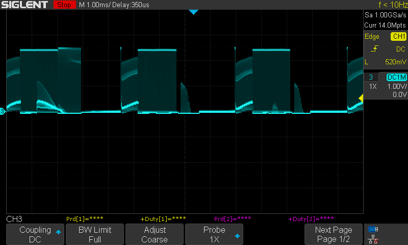
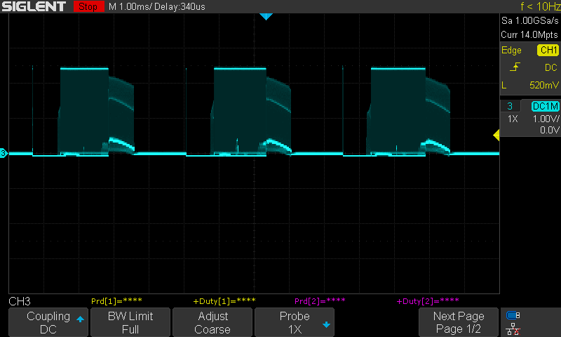
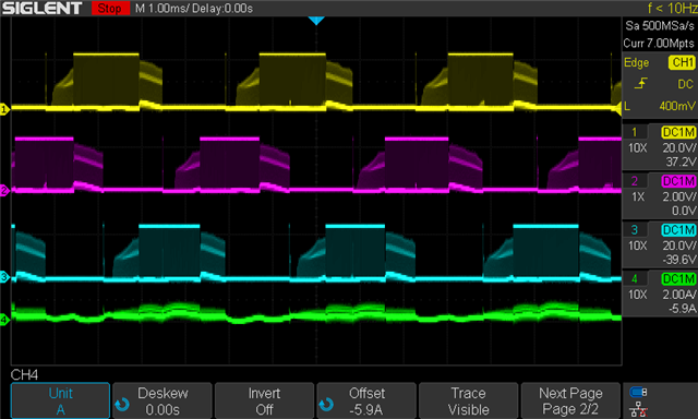
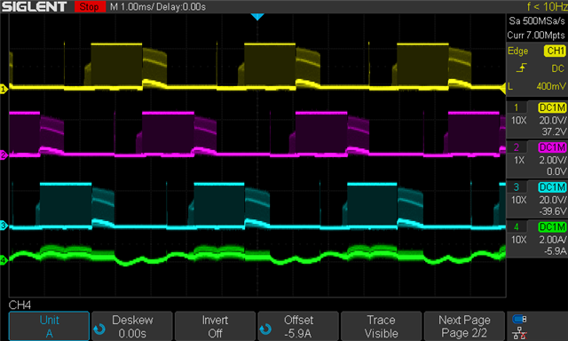
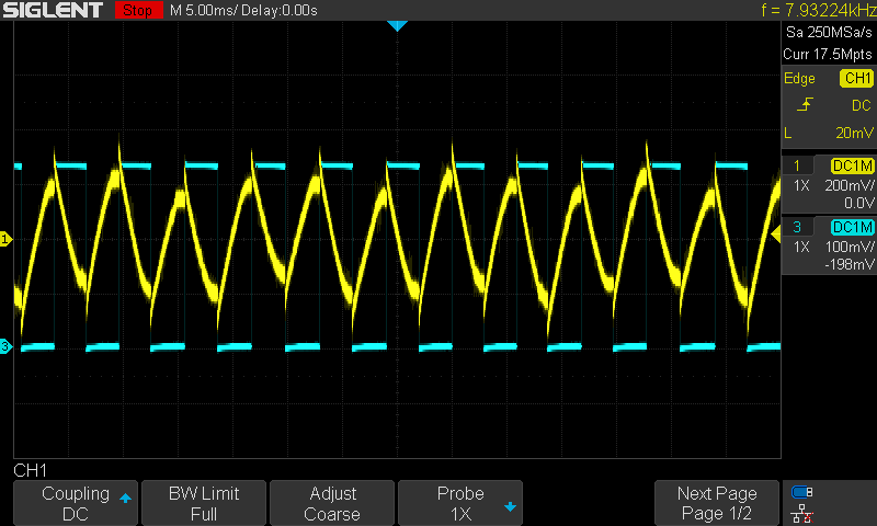
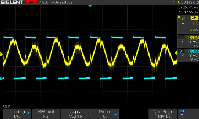
    2)  With our optimal tune (found using a brute force search against all parameters with load + rpm held constant) we get the following waveform. I am not sure if this is why the MCT is so finick with these motors but it does not look like a good trapezoidal waveform. I have checked phase resistance and measured the back emf while backdriving the motor, both look good to me. Top image is CW and the bottom image is CCW.

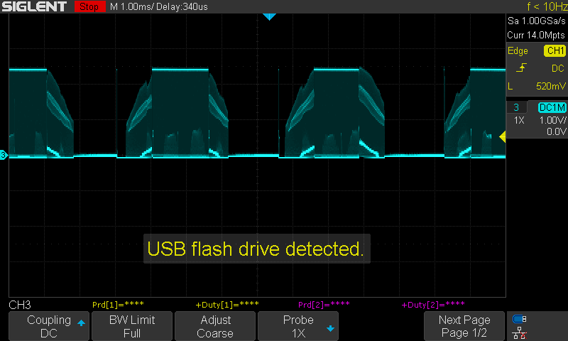
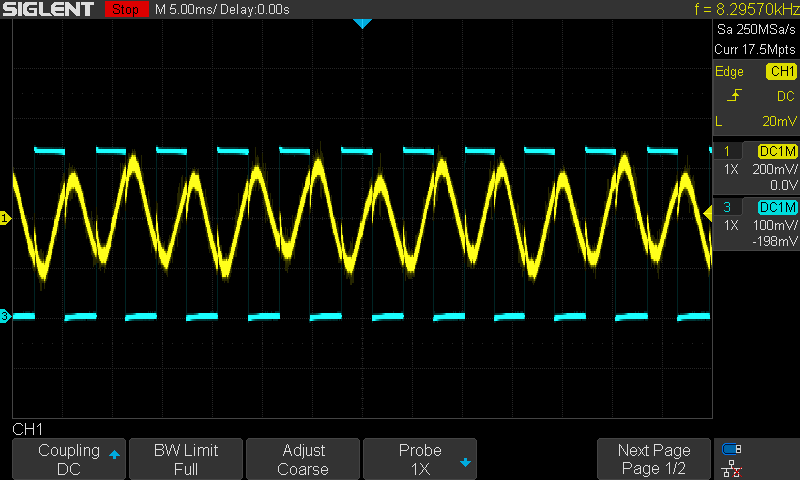
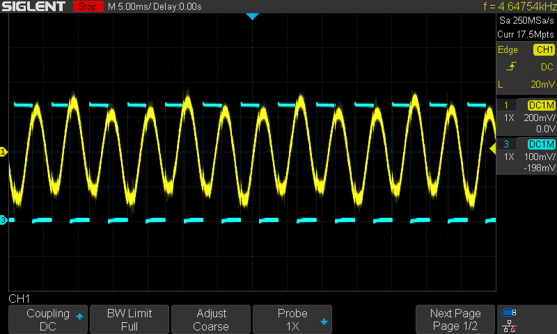
    Using one of the motors that is more robust to the parameters of the MCT we get this waveform:

    Do you have any thoughts about why some of our motors might not be playing as well with the MCT as others? We have tested these motors using a VESC and it seems to handle them much better without the need for any tuning. 

    Thanks

  • Hi Michael,

    Thanks for sharing waveforms. This is very interesting. 

    My best guess is to check the Hall sensor inputs back to the MCT8316Z for each motor. If the motor's Hall sensors are positioned a little bit differently for each motor, then there could be some uneven timings in the Hall comparator that yields poorer waveforms, like the first one you shared. The Hall sensors should be placed evenly between the motor phase coils, and the Hall input signals to the MCT8316Z should be even in their "active high" time. If they are not even, then there could be Hall sensor misplacement causing the poorer motor phase voltage waveforms. 

    Could you capture HPA, HPB, and HPC for a good motor and bad motor and compare the Hall timings?

    Thanks,
    Aaron

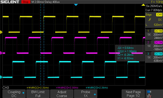
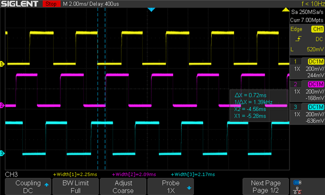
  • Here are HPA, B, and C. I captured data from two of the "bad" motors in both the CW and CCW directions and then collected the same for one of the good motors. Nothing looks particularly problematic to me based on their halls. For each motor I put the CW direction on the top and the CCW direction on the bottom. Note that with the bad motors we found that phase advance in the CW direction needs to be set to 0x07 / 30deg and in the CCW direction 0x00 / 0deg for best performance, sometimes the motors will not even spin if these are net set correctly for the direction the motor is spinning in.

    Bad Motor 1

    Bad Motor 2

    Good Motor

  • Hi Michael,

    These Hall signals appear fine across all motors. 

    What is your motor load when spinning the motor? Does the load change depending on the direction of the motor? For instance, ceiling fans have angled blades, so the load current will be different depending on the direction of the motor. 

    With different loads, the lead angle will need to be adjusted depending on the motor direction. 

    Thanks,
    Aaron

  • Those hall tests and waveforms are taken with no load other than the gearbox on each motor. I have also done some testing with 100Nmm constant load and I get similar results. The loads that I am working with should not have any directionality.

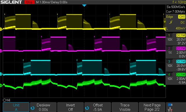
    I did some more testing today and noticed something interesting. I had set the motor to spin in the CCW direction with a 100Nmm load and a tune that was made for the CW direction.  The motor started out spinning in the CCW direction but suddenly switched to CW and turned the motor with very high efficiency. The waveforms looked really good too. It even outperformed the tune that I had found using exhaustive search with the motor set to spin in the CW direction. Here is a picture of that wave form (one of the phase currents in green):

    Comparing that to CCW (top) and CW (bottom) tunes it looks much better:

    Not sure if it helps but this is the configuration we have been using for the drivers:

    50kHz PWM frequency

    0x03 PWM Mode

    0x03 Slew Rate

    0x00 PWM Duty Select

    AAR and ASR active

    0x00 hall hysteresis (we are using digital halls)

    0x00 advance for CCW and 0x07 advance for CW

    0x09 for delay target

    Thanks

  • Hi Michael,

    Glad to see there is improved performance for motors after further tuning and testing! The motor phase waveforms look much improved compared to the initial ones. 

    Do you need any more assistance with this thread? If not, we can close it.

    Thanks,
    Aaron

  • Well the issue is that the best performance was achieved when I was sent he command for the motor to spin CCW but it switched shortly after spinning up in the CCW direction to CW. This is not very predictable behavior and is definitely not what a motor driver should be doing. Now if the motor actually spins in the direction I tell the driver to spin the motor in, the best I can do is the bottom two waveforms. I am not sure what motor characteristics could be causing the driver to act in this way since everything I have looked at so far seems to me to be ok.

  • Hi Michael, 

    Some of our team members are currently out on business travel for customer visits - 

    May take an additional 1-2 days to get back to you with a detailed response

    Best Regards, 
    Andrew 

  • Hi Michael,

    Does changing the PWM frequency have any effect, i.e. using 20kHz or 100kHz?

    Thanks,
    Aaron

  • We include PWM frequency as part of our tuning process and both 20kHz and 100kHz have lower efficiency on the motors we are tuning. 

  • Sorry I meant in terms of the lead angle, does the PWM frequency affect the lead angle calculation needed?

  • I just ran a test and it looks like all the PWM frequencies between 20-200kHz have the same optimal lead angle as the lead angle tuned for 50kHz. 

  • Thanks for the input. Let me talk with the team more to see if I can come up with more ideas on how to better predict and tune your motors. 

    Well the issue is that the best performance was achieved when I was sent he command for the motor to spin CCW but it switched shortly after spinning up in the CCW direction to CW. This is not very predictable behavior and is definitely not what a motor driver should be doing. Now if the motor actually spins in the direction I tell the driver to spin the motor in, the best I can do is the bottom two waveforms. I am not sure what motor characteristics could be causing the driver to act in this way since everything I have looked at so far seems to me to be ok.

    If we can't figure out the root cause, would you be open to sending your motor to us so we can run some testing ourselves?

    Thanks,
    Aaron

  • Sounds good. Sending over some motors shouldn't be an issue. Thanks

  • Sure thing. I am going to personally message you to see if we can resume conversation over email.

    Could you accept my friendship request?

    Thanks,
    Aaron

  • Hi Michael,

    Can you share the BEMF and Hall signal plot after spinning the motor by hand? This can help us measure the angle between the phase coils and Hall ICs.

    Thanks,
    Aaron

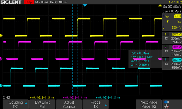
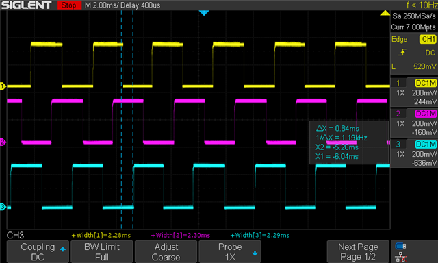
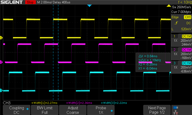
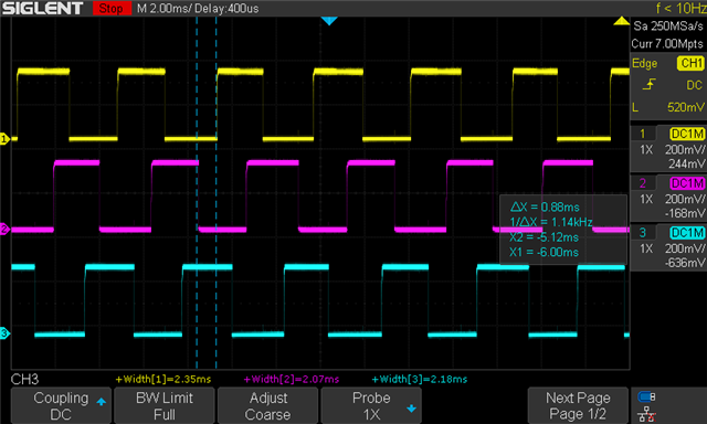
  • This should be every hall + phase pair in both the clockwise and counterclockwise directions. The motor was back driven with a drill. 

  • Hi Michael,

    Thanks for the additional information - our team will try to get back to you next week w/ an updated response

    Best Regards, 
    Andrew 

  • Hello. We have been able to resolve all the issues we were seeing by rotating the hall inputs counter to what was in the motor datasheet. Specifically we connected the hall for phase A on the motor to the input for phase B on the driver, B on the motor to C on the driver, and C on the motor to A on the driver. Doing this has increased motor efficiency and the motor now spins reliably under all parameter configurations!

    While we have resolved this issue for our application we would like to understand better why it was necessary to rotate the halls like this. We had issues with multiple motors from different vendors vendors and rotating the halls solves the problems we had with them when they were wired up according to their datasheets. I find it hard to believe all these motors had incorrect datasheets so I am wondering if there is another reason why this might be required. 

  • Hi Michael, 

    Glad to hear, and thanks for the update! 

    I will suggest to wait for Aaron's further feedback, since he's more familiar with the debug history.

    Best Regards, 
    Andrew 

  • Hi Michael,

    I spoke to my colleague about this to improve my understanding. 

    When Hall sensors are added into BLDC motor phases, there can be a slight "offset" depending on Hall placement. Typically, Hall sensors should have 0-degree placement or 30-degree placement, meaning that the Hall sensors should be placed no more than 30 electrical degrees behind (lagging) the zero-crossings of the phase current. If the current is positive, the Hall sensor should output a High or Low signal, and vice versa. 

    If the Hall active high voltages are lagging between 0-30 degrees due to Hall placement or motor inductance, then you can use the ADVANCE feature to introduce lead angle and delay the Hall signal inputs to the commutation logic to align the motor phase voltages with the motor phase currents. 

    If the Hall active high voltages are lagging more than 30 degrees due to Hall placement or motor inductance, then you'll need to use an MCU or intelligent Hall sensor devices that can correct the angle by adding a manual delay. 

    For both cases above, this assumes that all Hall sensors have the same offset, which means they are placed exactly the same distance apart if they are not placed 60 degrees between the motor phases. If they have different offsets, then you'll have to tune each Hall signal output accordingly with an MCU to align the motor voltage and phase currents together. 

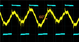
    In the waveforms above, I am not sure which plot goes with which phase and/or direction, but we can clearly see that the first 3 plots appears to show the Hall transition to HI leading the zero-crossing by 60 degrees, which means the Hall sensor needed to be switched to the next position (A --> B, B --> C, C --> A) to fix this. 

    If the motor manufacturer has the Hall sensors added to the motor, I would suggest reaching out to them to determine if this is an error or if these are 60-degree placement Hall sensors, which I know some motor manufacturers do but is not really common. 

    Hope this helps!

    Thanks,
    Aaron

  • Ok, this makes a lot of sense. Thanks for helping us get this all figured out the chip is working as intended now!