This thread has been locked.

If you have a related question, please click the "Ask a related question" button in the top right corner. The newly created question will be automatically linked to this question.

DRV8873H-Q1EVM: DRV8873H-Q1EVM

Part Number: DRV8873H-Q1EVM

Hello,

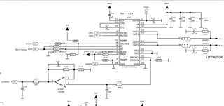
I have 2 different PCB, but both have same connection (shematic enclosure).

Both working, but if I drive them same PWM I get different Voltage/Current in motor ?

What can be wrong. If there is (however???) something different what can cost it ?

MVCC voltage is 30V and not dropping while driving motor.

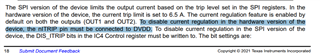
Driver ordercodes is DRV8873HPWPRQ1 

Drivers marking (top of the chip):

"GOOD"

8873HQ

91TG4

AE27

"BAD":

8873HQ

8ATG4

C8QP


Of course driver component works OK, and schematic have same problem, but I can't find error/difference  ?!?!

What can do that ?

Best Regards

-Kimmo-

  • Hi Kimmo,

    Thank you for your questions. Basically if your PWM input are same on two DRVs, OUTPUT PWM should be similar. 

    -Are you driving one motor in between J4-1 and J4-2 ?

    - What is the current level on both DRV? How much amp and how much delta?

    -Do you have output PWM waveform of both DRVs? Any difference? Any waveform (current or PWM) may helps me to understand your situation better.

    -Any possibility one of device has nFAULT=L while driving?

    One possibility is ITRIP operation. When ITRIP is enabled, ITRIP target is 6.5A.

    -nITRIP pin should be tied to DVDD(5V) to disable ITRIP. But your ITRIP tied to 3.3V. I strongly recommend to change it to DVDD as Datasheet's description.


    -IPROPI output should have some variation by device (datasheet page 7). If your system use IPROPI information for feedback loop, each device may has different level of current level. If your microcontroller change PWM by IPROPI information, each DRV may provide slightly different level of current. (I am not sure how much different level current you are seeing).

    Thanks,

    regards

    Shinya Morita

  • Hello Shinya and thank's you feedback.

    1. PWM is both PCB same. Frequency is about 25kHz and we use 30%-100% to drive motor.

    2. Motor is between J4-1 and J4-2

    3. Component and schematic should be same both PCB

    4. I can have FAULT signal that PCB what doesn't work (Output voltage on motor is too low !!)

    5. Both PCB ITRIP is unconnected ?? (but I can try to connect to DVDD)

    What about SR speed ? Can it somehow to limit motor driving voltage now ? 

    In Low speed mode PWM is on only 30% (12.5us) ?

    Best Regards

    -Kimmo-

  • Hi Kimmo,

    Thank you for your note. Unfortunately I did not get feedback for following two questions, especially 1). So I did not still get the whole picture what thier issue/difference of two units...

    1) What is the current level on both DRV? How much amp and how much delta?

    2) Do you have output PWM waveform of both DRVs? Any difference? Any waveform (current or PWM) may helps me to understand your situation better.

    So far my best guess is ITRIP pin. ITRP pin tied to VDD could be good to try. (Again, I do not have idea about whole picture of this issue).

    SR is just rise/fall time of output PWM. May not be main factor for motor current difference.

    thanks,

    regards

    Shinya Morita

  • Hi Shinya,

    1. Motor current is max 3.5A at start up, but after that is 1A...2A.

    2. PWM is same input and output. Output waveform is measured in OUT1.

    So motor current is so little (internal current limit is 6.5A !!!).

    I also have measured motor current oscilloscope current probe and there is no current spikes...

    Best Regards

    -Kimmo-

  • Hi Kimmo,

    Thank you for your feedback. 

    Peak is less than 6.5A of ITRIP. Without ITRIP, DRV does not control motor current, but DRV drives PWM output pulse.

    Depending on motor and motor load, motor current can vary even if same PWM output. I guess this is the reason. 

    regards

    Shinya Morita