This thread has been locked.

If you have a related question, please click the "Ask a related question" button in the top right corner. The newly created question will be automatically linked to this question.

DRV8873HEVM: DRV8873HEVM

Part Number: DRV8873HEVM
Other Parts Discussed in Thread: DRV8847

Hi,

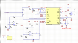
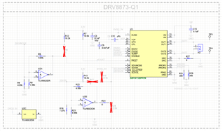
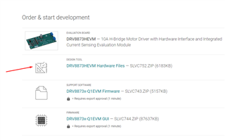
I need help related to DRV8873H EVM design files. Can anyone provide me DRV8873H EVM design files? I searched TI website and even if it says that it is DRV8873H EVM files but in actual it is S version files.

or

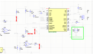
I need help to related to the function of OpAmp circuit created in S version EVM. I need a simple solution to control the DC motor speed and ON/OFF function. The specs of motors are as follows

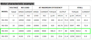
  • DC Brushed 12V Motor
  • 10A Current Rating
  • Need speed control
  • Simple interface with MCU i.e. PWM, EN etc.  NO SPI or I2C interface. I would prefer solution like DRV8847 because i used it many times for low current motors

  • Ali,

    Something like this?  

    https://e2e.ti.com/blogs_/b/industrial_strength/posts/easy-cruise-control-for-brushed-motors-using-bemf

    Would be easily adapted to DRV8873H to give you the current you need.  Or DRV8243/44/45.

    Regards,

    Ryan

  • Hi ,
    Thanks for the above link. It will definitely help me while designing the board.
    I would prefer to use DRV8873H because its cost is low.

    Can you help me simplify the above circuit for DRV8873H?

    What is the purpose of Opamp circuit? I believe it is because of 4 wire communication.

    One more thing, the actual product is a kid toy and I don't want to spend much cost on PCB. The targets cost for mass production is 5 to $7 and I also have some other chips. I am also open to use Mosfet solution because I need only two speeds. High , medium and off function.

    That's it

  • Hey Ali,

    For simplifying the circuit, I recommend looking at 8.2 Typical Application in the chip datasheet, this will show the minimum circuitry recommended to use the chip.  

    It looks like the Opamp is being used to adjust the slew rate on the Hardware (H) version of the EVM. Instead of using jumpers to select the resistances shown in 7.3.3.2 Slew Rate, the MCU sends certain signals to the op-amp that the chip then interprets as the desired values.  

    Here's a pic of which parts are populated/not for the Hardware version:

    Note that you won't need the op-amps for your circuit, you can follow 8.2 Typical Application schematic and put in the desired resistor values.   

    Regards,

    Jacob

  • Hi
    Thanks for your reply. 
    The schematic that you shared is actually the hardware version of EVM schematic which i am not able to find anywhere. Even at hardware EVM page, it says H version design files but when open then it is same as software.
    Can you provide me design files for hardware version?

    Also,

    I need your help to understand about slew rate concept.
    Is it means that how fast or slow the desired output available after input?

    Why we need low or higher slew rates?

    Thanks

  • I found the design files. It was in version. Sorry for misunderstanding.

  • Hey Ali,

    Glad you found the files, yeah it's just selecting the active variant.  

    Slew rate control allows you to tune in the best trade-off between efficiency (switching loss) and EMI generation.  Here's a StackExchange Discussion on the topic. At a faster slew rate you'll be more efficient because the FETs are both off for less time, but you'll generate more EMI.  

    Here's a video about slew rate in motor drivers:  https://training.ti.com/smart-motor-gate-drive-series-mosfet-slew-rate-control

    Cheers,

    Jacob

  • Hi 
    I setup resistors values for MODE and SR Pins. I put all recommended resistors using 0R resistor so i can do testing and choose the best out of it.

    Now, I need help in selecting IPROP and ITRIP pins resistors. I believe, we can fix ITRIP resistance as well instead of controlling it via MCU. As I am using hardware version. I am not sure, how to do it.
    Can you help me to define the resistance values for both?
    R(SENSE) = k × 5 V / IO
    Motor Specs:

    Also, What is the function of nOL pin?
    I want to use minimal control over MCU.
    Thanks
    1513.CIRCUIT.pdf

  • Hey Ali, 

    Looks like something went wrong with the PDF you uploaded, it is blank when I open it.  

    The nOL pin is the open-load diagnostic control pin as described in Pin Functions and 7.3.2.4.1 Open-Load Detection in Passive Mode (OLP) .  

    Work through section 7.3.1.4 Internal Current Sense and Current Regulation, it details how to choose those resistors and the other considerations that are required.  The range of current only goes up to 10A so you won't be able to measure 70A as shown in your table above, choose what you want to be the stall torque.  I recommend running your motor and measuring what the current normally is when not stalled, then choosing an appropriately higher value for the ITRIP current level.  

    Regards,

    Jacob T

  • I tied nOL with DVDD because I didn't understand much about this test. I don't want to make things complex so i disabled it. I believe it is for detection of the load.
    Also, If i consider EVM resistor values 390 ohm for IPROPl then current will be 

    RSENSE = ( k * 5) / IOUT

    IOUT = 5500/RSENSE
             = 5500 / 390
             = 14A
    The device can't provide current more than 10A so how this value is calculated?


  • Hey Ali,

    I think the EVM uses 390 ohms so that the IPROPI pin will always output something even if the customer runs the chip up to the limit.  

    The paragraph above the RSENSE=k*5V/Io equation says "The selection of the external resistor should be such that the voltage on the IPROPI pin is less than 5 V."  So I think they put 5V in the equation to show the max.  During normal load of let's say 6A, the output voltage would be 390Ω * 6A / 1100 = 2.12V.  

  • Ok,
    Let's say, I also use 390Ohm but how they are controlling Itrip because it is direction connected with MCU. In the harware version, How ITrip is setting current limit. There is no other components attached with it

    I read all datasheet but I couldn't find much detail or clear details about these two pins i.e. IPROPI and iTRIP.

    I need the driver to provide 8A of current and when current exceeded 9A then it should stop. Can you simply tell me the resistance values for it for both pins?
    The equation doesn't make sense to me.

  • I think , I can't use this IC anymore. My supplier told me that it is out of stock and 3rd party are selling it in $200 which is insane. All my time has been wasted.

  • Hey Ali,

    Yeah unfortunately TI does currently have some stock issues for high current integrated motor driver chips.  Sorry about that.  It looks like the highest current chip with stock I can find is the DRV8842 with just 5A peak current.  

    I was going to recommend you look at a gate driver and use external FETs since you need relatively high current (10A), but it appears those are all out of stock as well.  Regardless, I do recommend looking into a gate driver as a solution.  

    Regards,

    Jacob Thompson

  • Hi
    Can you help me to find a solution with only Mosfet? I don't want to spend money on chips because the product total cost is very low. It is a simple toy and i don't need huge efficiency.

  • Hey Ali,

    Sorry but that's outside of what I do here.  I support the brushed and stepper motor drivers.  TI typically tries to provide value in chips through features (integrated current sensing, current regulation, IPROPI, etc) and support, and we typically don't try to make the cheapest chip possible.  If lowest cost is the goal you might want to look into other brands of motor drivers.  If looking for just a FET solution I recommend looking around online and seeing if you can find something.  

    Cheers, 

    Jacob