Other Parts Discussed in Thread: DRV832X, DRV8323
Hi,
I'm using the BOOSTXL-DRV8323RS EVM module along side the LP-CC1352P7-1 EVM.
I'm attempting to run a rather basic code I wrote with the assistance of TI drivers and taking example from the "DRV832X_MSP.....".
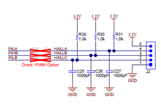
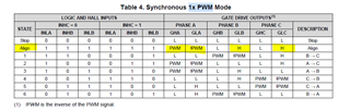
I wrote an SPI command to the driver control register to allow for 1xPWM mode. Right now I have a 45kHz PWM signal attached t othe INHA. INLA, INHB and INHL have HALL effect sensors connected to them, while INHC is the direction and INLC is the break. Enable, Direction and Brake are GPIO outputs on the CC1352, only Enable is high.
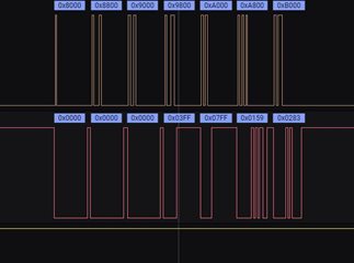
Given feedback from my logic analyzer the communication between the two seems to be working, I'm able to reset the registers to their default state at start of program and with a press of a button on the CP1352 I can send a command to the DRV to change to 1xPWM mode.
Reset Registers:
Send Command:

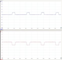
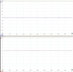
Feedback from SPI:

When the command was sent the motor twitched once and then haven't moved aftewards. I'm new with using the DRV8323 gate drivers and I would appriciate help in getting the EVMs working together.
Is there anything else I can send to help you with solving the issue? Let me know if you need extra waveforms.