


Other Parts Discussed in Thread: DRV8870
Hi team,
Here's an issue from the customer may need your help:
A DC motor with a drive peak current of 1.7 A which is around a couple hundred mA under normal use.
When using the DRV8870 to drive the chip, forward-reverse is good, and works fine when loaded on the device. After replacing the DRV8231A, the forward-reverse is also good when the motor is unloaded or when the motor is pressed by hand. However, if installed on the customer's device, the drive chip has no output.
The output current of the DRV8231A peak is 3.7 a and the maximum output current can be adjusted by the RIPROPI resistor. Customer has tried 2K, 1.5K, 680Ω with 1.1A, 1.466A, 3.23A threshold current respectively. But once it's mounted on the device, there's no output.
The input PWM waveform has been tested 1K, 10K, 50K, and the duty cycle is 50%, failed again.
DRV8870 operates with output current varying between 180-600mA (load always changing) and output voltage M+=17.6V, M-=1.36V (measured by multimeter). DRV8231A has an output voltage of 0 and 400-mA change in current when turned on. The current then becomes more than 100 mA, and then it becomes 0 in a moment, and the M+ and M- output voltages are also 0. When the motor is unloaded, the DRV8231A output voltage is the same as the DRV8870.
The motor stops after a current meter is connected in series to the circuit of the DRV8231A.
The circuit is as follows:
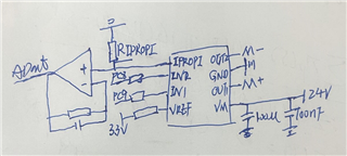
PC8, PC9 is connected to the pins of the MCU, M+,M- is connected to the positive and negative input pins of the motor. A voltage follower is connected to the output of pin 1.
Could you help check this case? Thanks.
Best Regards,
Cherry

