This thread has been locked.

If you have a related question, please click the "Ask a related question" button in the top right corner. The newly created question will be automatically linked to this question.

DRV8323: Vgls Max if VM is >24V

Part Number: DRV8323

Hello,

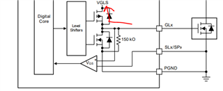
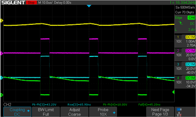
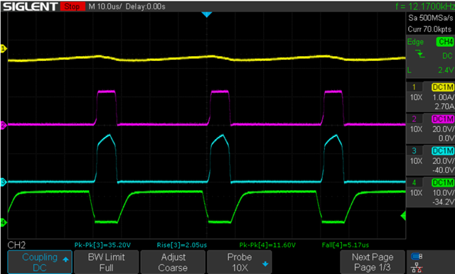
We were just wondering how the Vgls regulator works because it has the potential to damage our FETs. The datasheet does spec Vgls for VM > 12V... Our VM can go up to 35V and we want to ensure the Vgls doesn't go over 20V...

I saw another thread where a similar question was asked 5 years ago but no one answered.

Regards,

Jerome

  • Hi Jerome,

    VGLS is an internal regulator powered from VM. VGLS is typically 10-12V output for the low-side gate driver supply. You can use higher VM supply voltages and there will just be a larger voltage dropout across the VGLS regulator, causing more power dissipation. 

    The goal is to ensure that VGLS does not get backpowered to VM. The VGLS output should not exceed 20V so proper VGLS considerations should be implemented such as placing the VGLS bypass cap close to the device, using a 25-V rated capacitor for the VGLS bypass cap, using appropriate IDRIVE settings, and ensuring voltage spikes do not occur on GLx so that it does not go through the sneak body diode path below.

    Hope this helps,

    Aaron

  • Hi,

    I did quite a bit of extensive testing a while back on the eval for the DRV8323 and using a VM of 24V I was seeing GLx range between 12V to 18V depending on the test I was doing. But it looks like it was a function of how much IDRIVE current is selected. This leads me to believe that the jump to 18V might be due to trace inductances between the Gate driver and the FETs.

    This is with the highest gate IDRIVE settings

    CH1: IOUTA, CH2: VOUTA, CH3: GHA, CH4: GLA

    This is with the lowest gate IDRIVE settings

    CH1: IOUTA, CH2: VOUTA, CH3: GHA, CH4: GLA

    But if the LDO for the Vgls is truly set to no more than 12V then that's all I need to know. From the datasheet it looked the like the Vgls scaled with Vm...

    Regards,

    Jerome

  • Hi Jerome,

    If your IDRIVE settings are too high and there's high trace inductance in the gate drive outputs, then because of the equation V = L * di/dt, high IDRIVE settings may cause too high of a change in gate drive current (di/dt) so that if there's too much inductance in the gate drive outputs (L) then this can cause an increase in voltage (V). 

    From your IDRIVE settings below, you may need to choose an IDRIVE setting that is appropriate in value based on your MOSFET's Qgd value and the amount of gate drive current that can be supported based on gate driver layout.

    For more info, please see this E2E FAQ: e2e.ti.com/.../faq-selecting-the-best-idrive-setting-and-why-this-is-essential

    Thanks,
    Aaron