This thread has been locked.

If you have a related question, please click the "Ask a related question" button in the top right corner. The newly created question will be automatically linked to this question.

DRV8825: DRV8825 Fstep and mode and others function

Part Number: DRV8825

Hi Team,

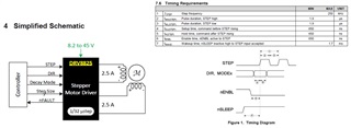
1. In the Fstep of the timing requirement, I want to confirm whether it is a PWM clock, so the requirement for DRV8825 is below 250Khz?
2. As shown in the diagram, is the step size controlled by mode 0~3?
Signals and controls for this part of Decay Mode & DIR?
3. It may be troublesome to provide EVM circuit/BOM (especially if there is a Prefer motor coil)

  • Kevin,

    1)  Fstep is the clock to STEP input.  It must be below 250kHz, correct.  On each rising edge on the STEP input, the motor will move one step.  

    2)  No, this table is just trying to show that the DIR, MODE pins need to meet the "setup" times before a STEP is used (rising edge).  Normally, the Decay and MODE pins are fixed on the board.  You would only control the DIR and STEP pins.  

    3)  I don't understand the question...can you please clarify?

    Regards,

    Ryan