Other Parts Discussed in Thread: DRV8801
hello.
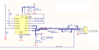
I'm using the DRV8800PWP, and I'm investigating a failure that causes the ITRIP to operate at half the setting or the IC to stop outputting.
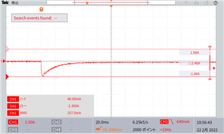
The operating conditions are as follows.
Rsense: 0.43Ω (Itrip = 1.163A expected)
Load: DC brushed motor
Starting current, stopping current: 1.5A
Working current: 0.2A
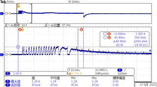
Shows the current waveform during operation.
Q1: Should I avoid using the DRV8800's ITRIP for current limiting?
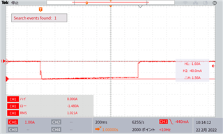
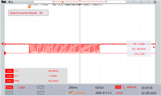
・The starting current of the motor in use exceeded ITRIP.
・When the motor is locked, the state continues to exceed ITRIP for several seconds until the software stops.
Q2: Will the IC be damaged if I continue to operate it as is?
Q3: I'm thinking of further lowering ITRIP to keep the current down when the motor is locked, but should I avoid this?
Regards,
Kensuke Suzuki