This thread has been locked.

If you have a related question, please click the "Ask a related question" button in the top right corner. The newly created question will be automatically linked to this question.

DRV8701: DRV8701PRGET is burning up within second in Rev.2

Part Number: DRV8701

Hello TI - Team,

we have a problem with a motordriver that we have designed.

We are driving 2 x 24v @ 15A linear actuators with integrated hall sensors. Those intergrated hallsensors provide us with a 5v squarewave feedback which we use to sync the movement between those actuators.

Our micro contoller is an Ardunino RP2040 - we provide a 3v - 1kHz PWM signal to IN1/IN2 for forward drive and reverse polarity. The % of the duty cycle is used to reduce or increase the speed of the actuators to keep them in sync.

One of my co-workers designed the circuit and a PCB developer in China designed the PCB/component layout for us and produced our first prototype.
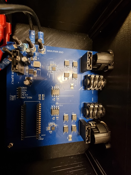
The first prototype worked almost 100%...motors were going fine...syncronisation worked flawless but we had some issues with the 5v rail supplying the Arduino.

So we redesigned the circuit. Our designer implented a schottky diode (D2) and increased the capacitance of a capacitor within the DC/DC drop down circuit.

He implented as well an opto isolation IC (6N137s) with integrated 5v/3.3v logic conversion to isolate the feedback signal from the actuators.

Now my big question.

 /cfs-file/__key/communityserver-discussions-components-files/38/ORIGINAL-Schematic_5F00_rp2040-tiltvegg_5F00_2021_2D00_10_2D00_28.pdf

The first design has power supply problems regarding Arduino RP2040 but we do not have any issues with the DRV8701P drivers.
The actuators are driving forward and backward as we planned....it is audible that the motor speed is corrected (brake) and the acutators are going in sync.

But the 2nd version is buring the DRV8701P basically instantly and we do not understand why. We did not made any modifications to the DRV8701P circuit and we didn't changed the software....we implemented those 2 opto isolation IC's (U2 and U10), added the schottky diode, increased cap and replaced the contacts for the feedback signal from a 3.5mm to a 6.35mm jack socket.

/cfs-file/__key/communityserver-discussions-components-files/38/wall-contoller-Rev.2.pdf

Could i ask ? Is there an obvious design flaw ?

Those IC are becoming unobtanium and the prices are sky high. We managed to damage 8 chips during troubleshooting and all of those chip are permanently damanged as they are getting hot as the sun as soon as they are powered up. I would appreciate if the TI team could take a look at my design and support me on my way.

Best regards

Christian

  • Hi Christian,

    I will take a look at your design but any possible explanation for the device damage. I will get back to you within 24 hours.

    Regards,

    Pablo Armet

  • Hi Pablo,

    much appreciated. I am looking forward to hear from you !!! 

    Best regards 

    Christian 

  • Hi Christian,

    I think the Schottky diode may be problematic. How are you driving the motor during the current decay phase? Cost or Brake? During Coast, the FETs are disabled and energy in the motor coil will flow back to VCC via the body diodes. However, the Schottky diode will prevent the current from flowing back. This may cause a large negative voltage on the OUT pin of the device. This phenomena is called inductive kickback. The best way to fix this is by adding a diode between VCC and GND.

    The current of the motors is 10A. Is this for each of both and is this the normal operating current or peak current? The diode (D2) has a maximum rectified forward current rating of 1A. I don't think this is enough. Can you explain why this diode was selected. Can you try removing this diode?

    Regards,

    Pablo

  • Hi Pablo,

    first up....thanks for your fast reply.
    I am pretty sure we use "cost" mode. We cut the power to the motors until they stop.

    Yes...each motor draws about 10A under full load. Average about 8A. The reason why the Schottky diode was added was to fix the power problem for the RP2040. As soon as the polarisation for the motors changed we ran into power problems. The RP2040 just restared. So my co-worked decided to add the Schottky diode but why he decided to use that diode i have to check with him. I can try to remove the Schottky and test the system.

    There is another thing that we are a bit worried about. The feedback signal from the actuators is used to sync the movement. We count the pulses as soon as the actuators are moving.
    If we use a higher PWM frequency than 1kHz we expirience lots of noise within the feedback circuit. Our feedback counts are far off from what we would expect.

    As an example.
    The actuators are returning 15 pulses for each moved millimeter. 10mm movement = 150 pulses

    Feedback pulses are correct when we drive the actuators at 1kHz  but as soon as we increase the PWM frequency and we pass 5kHz the feedback signal starts to "run" away.... instead off 150 pulses we count as example 623...but only if the PWM is above 5kHz...everything under 5k looks fine.
    Is there a chance for a faulty design....considering that the DRV8701 should be able to handle 100Khz ?
    I will remove the Schottky and update you.

    Thanks and best regards

    Christian

  • Christian,

    It is a US holiday today...expect a response tomorrow.

    Regards,

    Ryan

  • Thanks for the update. Enjoy your holiday !!!

  • Today is a US holiday.  Team will respond tomorrow.

  • Hi Christian,

    Apologies for the late reply.

    Feedback pulses are correct when we drive the actuators at 1kHz  but as soon as we increase the PWM frequency and we pass 5kHz the feedback signal starts to "run" away.... instead off 150 pulses we count as example 623...but only if the PWM is above 5kHz...everything under 5k looks fine.
    Is there a chance for a faulty design....considering that the DRV8701 should be able to handle 100Khz ?

    what actuator are you using, can you share the datasheet? Also, is the duty cycle in both frequencies the same? 

    I can try to remove the Schottky and test the system

    Please do and let me know the results.

    Regards,

    Pablo Armet

  • Hi Pablo, thanks for your feedback. I am not at the office today. The Schottky is removed but no test's have been performed. I will update you tomorrow with the results. 

    The actuator we use is called Remore RE803. I do not have more information's except the mentioned 24v - current draw = max10A and the integrated hall sensor. 

     Wiring Method RE803.pdf

    what actuator are you using, can you share the datasheet? Also, is the duty cycle in both frequencies the same? 

    Yes the duty cycle is the same on all tested frequencies.

    I send you the test results tomorrow. 

    Thanks and best regards 

    Christian 

  • Hi Pablo, I tested the circuit after I removed the Schottky and no more DRV8701's burning up but I can see that the IC is still getting pretty hot. I used Isopropanol to check how fast the fluid evaporates and does not take long before the Isopropanol layer is gone.  Max. 60 sec. 

    There are still issues regarding the PWM frequency...as soon as I pass the magic 5kHz range things are going crazy. 

    I have to discard the circuit. There are too many issues within the design and as mentioned before...the DRV8701P is getting too expensive. 

    Thanks Pablo and the rest of the TI team..

    Best regards 

    Christian