This thread has been locked.

If you have a related question, please click the "Ask a related question" button in the top right corner. The newly created question will be automatically linked to this question.

DRV8703-Q1: how to apply PWM signal

Part Number: DRV8703-Q1
Other Parts Discussed in Thread: DRV8811

Hi Expert,

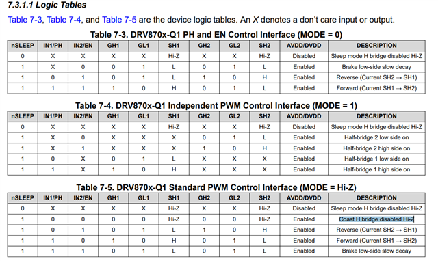
I have two questions about DRV8703-Q1.

1. Why do we need "Coast H bridge disabled Hi-Z"? What kind of function does it achieve?

2.For below three modes, PWM signal is fed to which pin, EN or PH, in order to achieve speed changing? Thanks.

BR,

Elec Cheng

  • Hey Elec,

    1. Coast mode allows the motor to spin down slowly instead of quickly bringing the motor to a stop.  This will result in the least mechanical stress on the load and the shaft, as it will spin down as if the motor was spinning and was disconnected from the motor driver.  Depending on the inertia of the load this could happen quickly or take several seconds to stop.  Here's a more thorough description of coast mode from this E2E post:

    In coast mode, the output terminals are set to High-Z state (open) as shown in Table 1 of the datasheet. The current in this case will go into fast decay mode. In fast decay mode, the current is not maintained in the coils and instead flows back to the input source (input bulk capacitor). Effectively, the motor will continue to keep spinning and that is why it is called "Coast". If input cycles are continued to be sent to device, the motor will be accelerated during the ON time and will "Coast" during the OFF time and this will continue to happen until there is a balance between the energy added during the ON time and the energy dissipated during the OFF time. If input cycles are stopped being sent to device, them the motor should "Coast" to a stop but the time it takes to stop will depend heavily on friction. 

    2. Apply the PWM signal to IN1 or IN2.  Use the other pin to choose whether it coasts during the off-time of the PWM signal or if it low-side brakes - for example, if you PWM IN1 and set IN2 to HIGH(1) then you'll be driving in Reverse and Brake low-side slow decay if I'm reading the table correctly. 

    Regards,

    Jacob

  • Hi Jacob,

    I know this may like a little ridiculous but do you which mode is used in window anti-pinch application? Both the customer and I don't know clearly about this usage...The H-bridge works pair with below analog solution. The MCU detect the ripple to judge if the motor(window) is pinching. Do you or your colleague have any idea about this? Thanks a lot for help!

    Automotive Brushed-Motor Ripple Counter Reference Design for Sensorless Position Measurement.PDF

    BR,

    Elec Cheng

  • Hey Elec,

    I think most vehicles just use current sensing to detect pinch, not full sensorless position measurement. The DRV8703 has the SO pin that is the amplifier output, and section 7.3.5 Amplifier Output (SO) details how this can be used to calculate the current.  Then an MCU would be used to detect when the current was above a threshold and pause the motor movement.  

    Here's a tutorial about using current sensing for stall detection: [FAQ] How to detect motor stall using current sensing

    And here's a design guide for brushed DC motor stall detection:  https://www.ti.com/tool/TIDA-010073

    For stepper motors many of our drivers have stall detection built in.  Here's an example for the popular DRV8889:  Sensorless Stall Detection With the DRV8889-Q1

    Let me reach out to a coworker with more experience in automotive applications and see if he has further insight specific to vehicle windows.  

    Regards,

    Jacob

  • Hi Jacob,

    Thanks for your detailed reply and look forward to your feedback! Thanks again.

    BR,

    Elec Cheng

  • Hey Elec,

    I'm still waiting on my coworker to get back to me about the car windows.  

    Do you have any more details on your design/plans/specs you could share?

    Regards,

    Jacob

  • Hey Elec, 

    Both stall detection (using just the raw current information) and counting ripples can both be used for the anti-pinch.  

    Ripple counting gives you the added benefit of doing a “soft close” at the end of travel.  So, you can rocket the window up and slow it down at the end when an obstacle would be encountered.  The rubber gasket may last longer when the window moves slower into final position.  

    If you want the window to use as fast as possible we recommend adding ripple counting to determine if you are at/near the end of travel, and slow down before a stall is detected.  This is a more elegant solution than slamming the window into the gasket and detecting stall and stopping the motor very quickly.  

    Regards,

    Jacob

  • Hi Jacob,

    Thanks for sharing these. If i understanding correctly, Hi-Z and Brake low-side slow decay are two different way that the motor speed down. The main difference between them are the current path and energy conversion. 

    I see your latest explanation but I still don't find the relation about these two ways. How can they decide which way for decay, fats or slow? What kind of parameter they may need consider? Thanks.

    BR,

    Elec Cheng

  • Hey Elec,

    Check out this document: Application Note:  Current Recirculation and Decay Modes

    And https://www.ti.com/lit/wp/slyy066c/slyy066c.pdf#page=3

    And here's a good answer about them:  

    Decay mode setting usually plays obvious effect on high degree microstepping, such as 1/4 to 1/256. It is true that you can hardly tell any difference in full step as the decay mode changes.

    For more about the decay modes setting, you can first refer to most of the DRV8x datasheet including DRV8811 and understanding the fast, slow, mixed decay function. The reason and purpose we do different decay modes setting is to let the current go down or up as quickly as possible according to the setting value determined by Micro stepping index. Usually, if the current is regulated the more sinusoidal, the more smooth running, and less noise and torque ripple.

    Generally, Fast decay usually is needed for high inductance motor, high running speed, high degrees micro stepping which all need the current change quickly. But fast decay brings audio noise sometime, also more heat and switching loss.

    Slow decay will have less audio noise and better output torque level at low speed running.

    Sometimes this is best to test in the complete assembled system, as many factors can affect how the motor runs between friction, inertia, vibrations, speed, etc.  

    Regards,

    Jacob