This thread has been locked.

If you have a related question, please click the "Ask a related question" button in the top right corner. The newly created question will be automatically linked to this question.

DRV8876: Device failure

Part Number: DRV8876

Hi Team,

Can you please help us regarding the issue with DRV8876PWPR below? According to our customer,

Several DRV8876PWPRs burned out during a lab test with a debugger attached and also in a real product during a test run.

There are numerous cases of failure of the discussed component in the course of software debugging. During debugging, both DRV8876PWPRs used are loaded on brushed motors. These motors are unloaded and draw 150-200 milliamps. Breakpoints are heavily used during debugging. DRV8876PWPR is connected to the microcontroller with 4 lines, as can be seen in the attached diagram. To check, we cut off the nFault line from the microcontroller, but this did not affect the result - the components burned out anyway.

There are also several cases of failures when used in the final product. We design and manufacture robotic pool cleaners. In these cases, the robot functioned under periodic heavy loads on the motors. During the investigation, no traces of thermal effects were found either on the DRV8876PWPR or on the motors.

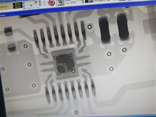
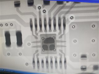
Please see attached schematic diagram and PCB layout. Can you please help identify the possible cause of this failure?


Regards,

Danilo

  • Hello Danilo,

    I will look through the schematic to identify possible root cause. I will get back to you within 24 hours.

    Regards,

    Pablo Armet

  • Hi Danilo,

    I don't see any issues with the schematic that could explain the damage to the IC. However, I did notice the exposed thermal pad in the layout is small compared to the DRV8876EVM. During heavy loads, the current will spike up and the heat concentrated on the exposed thermal pad. Increasing the thermal PAD size and the number of thermal vias will help keep the temperature low during high loads.

    The current of the motor under heavy load? Do you have a picture of the damaged IC? Are the ICs being damaged right at when motors sre driven or after some time after? Is this problem occurring in more than one board?

    Regards,

    Pablo Armet

  • Hi Pablo,

    As for the size of the thermal pad. In our application, the thermal pad is connected to an extensive layer of GND by the number of vias. During the lab test, we did not see any significant heating of the DRV8876. Among other things, most DRV8876 failures occurred during software debugging when the motors were running without load (150 - 200mA).
    In terms of numbers, 2 units of DRV8876 failed under load, as part of a robotic cleaner, and 6-7 units during software debugging. I am attaching 2 pictures of 3 failed DRV8876. Unfortunately, the pictures are not very sharp. When operating the DRV8876 as part of a robot, the motor drivers worked for over 300 hours. DRV8876s that failed during the software debugging worked for several tens of minutes before failure.

    I shared some photos of the damaged IC thru private message.

    Regards,

    Danilo

  • Hi Danilo,

    In terms of numbers, 2 units of DRV8876 failed under load, as part of a robotic cleaner, and 6-7 units during software debuggin

    Have they been able to consistently cause the failure? I'm trying to understand if this is a systematic failure (meaning repeatable). 

    DRV8876s that failed during the software debugging worked for several tens of minutes before failure.

    Can you ask them to provide a detailed procedure as to when the breakpoints are being used? What happens to nSLEEP, power supply voltage, and other control pins of the driver when breakpoint is triggered?

    Regards,

    Pablo Armet

  • Hi Pablo,

    Please see the comment of our customer below.

    With regard to the repeatability of failures, failures in the composition of the final product are relatively rare. We tested about 15 robots under different conditions and only 2 of them failed due to the failure of the DRV8876(s). At the same time, our firm has produced several thousand robots with this PCBA. At this stage, there is no feedback yet. Regarding the failure of the DRV8876 during software debugging, 100% of the PCBAs used for debugging failed due to the failure of one or both components. Failure can happen after several tens of minutes or hours of debugging work. Of course, this depends on the intensity of work on debugging the code.
    As for the debugging process, all supply voltages are always present on the PCBA, which also means that nSLEEP is always pulled up to 3.3 volts. As for the control signals, it is difficult to say in what condition they are. The DRV8876 drivers have been debugged for a long time and work is underway to debug the behavior of the robot in the pool, i.e. routine at a higher level. Most likely, the direction control pin remains in the same state, but the PWM generator stops working.
    PCB1-1 & PCB1-2
      
    PCB2-1 & PCB2-2
      
    Regards,
    Danilo
  • Hey Danilo,

    I don't see any visible damage on either DRV8876 in the above pictures or the private message pictures.  Could you tell us more about the nature of the damage or how they blew up?  Like are certain pins shorted to each other or shorted to ground now?  Specifically for the software debugging failures.  

    Does the MCU still work after the DRV8876 works, so you could still go into debugging but the motors just won't spin?  

    I checked the lot trace information for the chips in the image and they are legitimate.  

    Lastly, can you verify that the 3.3V rail is stable during software debugging?  Make sure it doesn't dip too much below 3.3V.  Should be fine with your 1A LDO but just want to check since a lot of things are attached to it.  

    Regards,

    Jacob

  • Hi Jacob,

    Below is the response of our customer.

    First, there is no visible damage on either DRV8876. Testing without power with a multimeter revealed no short circuits on both outputs and inputs, neither to each other, nor to ground. When power is applied, both DRV8876s start to heat up even without a connected load. A more detailed investigation using an oscilloscope will be carried out later.
    I want to add that DRV8876 did not burn down together, but one by one, one after another. Each of them began to work intermittently, and then failed.

    Yes, after the failure of DRV8876, the MCU continued to work as usual, but without motors. But this makes debugging difficult.

    Thank you for checking these chips for legitimation.

    Yes, the 3.3V rail is stable during software debugging, with no visible dips.

    Regards,

    Danilo

  • Hey Danilo,

    That's odd, sorry you're having this issue and that we're having to ask so many questions.  Interesting to have no short circuits on inputs or outputs.  

    After a failure, if you replace the DRV8876 chips does the board work like new again?  

    I am also curious on if this same issue can occur if you use the EVM.  I'm guessing it's a different MCU, so do you think you'd be able to jump wires over to the DRV8876 on the EVM and see if the same failure occurs?  I'm trying to rule out PCB/schematic issues relating to the DRV8876 chip. 

    Cheers,

    Jacob

  • Hi Jacob,

    Please see the response of our customer below.

    First, if you replace all failed DRV8876 chips, the PCBA functionality is fully restored. But if you continue to use this board for software debugging, then DRV8876 chips fail again after some time.
    As for replacing the microcontroller and PCB with EVB, there is no need to do so. A year ago, we were forced to replace the MCU ST with the MCU GigaDevice. And before that, we developed a board with 2 DRV8876 chips controlled by MCU ST. Everything worked fine, including when debugging software. Thus, 3 components have changed: MCU, firmware and PCB layout. Where is the problem? What can damage the DRV8876?
    I contacted GigaDevice technical support for help. What questions, do you think, they need to ask in order to understand the impact of the MCU in debug mode on damaging the DRV8876?

    Regards,

    Danilo

  • Hey Danilo, 

    I noticed you have a direct connection from the MCU to the DRV8876 input pins, without any current-limiting resistors in series with the connection.  I recommend adding a 100Ω-1KΩ resistor in series to limit the current on the logic level input pins (IN1, IN2, nFAULT, nSLEEP, PH/IN2, PMODE). I wonder if those pins are having too much current put through them and eventually damaging the chip.  Make this change a priority for your next version of boards.  

    The only things that should damage DRV8876 is exceeded datasheet recommending operating conditions.  Breakpoints on the MCU during debugging shouldn't damage the DRV8876 since it is a separate chip.  We are still internally discussing this issue and trying to come up with another cause of failure.   

    I would ask GigaDevice whether any IO pin functionality changes during debug mode during a breakpoint - are any internal protections or current limiting disabled?  Do any pins have internal pull-up or pull-down resistors that are activated during debug other than SWDIOX/SWCLK?  

    Regards,

    Jacob

  • Hi Jacob,

    I just received this email from our customer.

    Unfortunately, I haven't been in the office for a while so I couldn't quickly check your solution. Now the solution is tested but does not work as it should. 1kΩ resistors were installed in series with control lines IN1 and IN2 in both DRV8876 controllers. Within 1 hour of operation, one DRV8876 stopped working.

    Regards,

    Danilo

  • Hello Danilo,

    Thanks for providing the information from customer.

    Based on the information so far, the issue is mainly happening during software debug. Let's focus our investigation on what is occurring during the software debug. Like Jacob suggested, does the IO functionality of the MCU change during a breakpoint. Specially on the IOs connected to the motor driver. Are the GPIOs connected to the DRV pins going low or high-z during a breakpoint? 

    Regards,

    Pablo

  • Hi Pablo,

    Our customer is out of office for the holidays until October 18th, hence, has no access to their test equipment.

    Please see his email below.

    Regarding your question, the answer from GD tech support is: In Debug mode and the core is halted, the GPIO configurations remain unaffected. However, the voltage level on the outputs would not change (High or Low) at the moment the core stops.
    For the TIMER/PWM – this would depend on the software configuration.

    For example, if the DBG_CTL0_TIMER1_HOLD bit in DBG control register (DBG_CTL0) is set and the core halted, the TIMER1 counter stop counting and the PWM outputs of all channels are stopped as well.

    Just before I went on vacation, another DRV8876PWPR burned out during debugging. And at that moment I did not use break points. Due to a bug in the program, the motor control switched the direction of rotation of the motor with a higher frequency than usual. It is possible that this was the cause of the damage.

    Regards,

    Danilo

  • Hi Danilo,

    Thanks for relaying the information.

    For example, if the DBG_CTL0_TIMER1_HOLD bit in DBG control register (DBG_CTL0) is set and the core halted, the TIMER1 counter stop counting and the PWM outputs of all channels are stopped as well

    So when the PWM outputs are turned off, what is the value of the INx signals? Do the PWM signals remain in the last value before the breakpoint is triggered? or does the value drop to 0V. 

    Just before I went on vacation, another DRV8876PWPR burned out during debugging. And at that moment I did not use break points. Due to a bug in the program, the motor control switched the direction of rotation of the motor with a higher frequency than usual. It is possible that this was the cause of the damage

    If the voltage across the motor suddenly changes, let's say it is in forward direction and suddenly IN1 and IN2 change so that the direction is changed to reverse, the inductance in the motor is going to prevent the current from suddenly going in the reverse direction. The diagram below shows this operation. Transitioning from normal operation to fast decay is analogous to transitioning from forward to reverse current direction. When switching to reverse direction, the current will keep going in the same direction and the current will flow back to VM until the current decays past 0A and starts flowing in the opposite direction (reverse). It may be possible that if the transition occurs at a point when there is a large amount of energy in the motor coil, the current flowing back to VM causes the supply voltage to spike above the recommended operating voltage. 

    I believe the are driving near the abs max VM voltage and the added energy back to VM is causing an overvoltage condition. 

    Regards,

    Pablo Armet

  • Hi Pablo,

    Our customer went on a vacation and just returned to work. Please see his comment below.

    I apologize for the delay in reply. First of all, I thank you for the detailed answer in your last letter. On our return from vacation we have another pool cleaner with a burnt out DRV8876. The failed DRV8876 component had physical damage to the case, most likely from overcurrent. This is the second product with similar damage. After brainstorming with my team, it was decided to reduce the level of hardware protection from 2.7 to 1.9 Amps (ipropi resistor changed to make this). Several robots upgraded in this way are being tested over the weekend. Regarding the failure of components during debugging (we have more than 10 such cases), a code review was made to clarify the problem. After some changes to improve reliability, laboratory tests will be repeated early next week.

    Tests with a decrease in the protection operation current to 1.9A ended unsuccessfully. One of the DRV8876 burned out (see attached photo). In the next step, we changed the protection threshold to the level of 1 ampere. 24 hours after the start of the experiment, both upgraded products continue to work.
    It is not clear to me how to calculate the continuous maximum current. How can we calculate it in order to choose the optimal current protection threshold?

    Regards,

    Danilo

  • Hi Danilo,

    It is not clear to me how to calculate the continuous maximum current. How can we calculate it in order to choose the optimal current protection threshold?

    The current regulation limit should be chosen such that the RMS current does not generate high temperatures to the IC. Another variable to consider is the inrush and stall currents of the BDC. during motor stall and start-up, the current should be limited to below the OCP value and above the nominal RMS current of the motor.  

    Tests with a decrease in the protection operation current to 1.9A ended unsuccessfully. One of the DRV8876 burned out (see attached photo). In the next step, we changed the protection threshold to the level of 1 ampere. 24 hours after the start of the experiment, both upgraded products continue to work.

    Interesting... what is the typical inrush and motor stall currents for the motor you are using? 

    After some changes to improve reliability, laboratory tests will be repeated early next week.

    Keep me updated on the results of the tests.

    Regards,

    Pablo Armet

  • Hi Pablo,

    Here is the feedback of our customer.

    Thanks for the info. In any case, the 1 amp current limit test failed - one of the DRV8876 burned out. At the same time, some components powered by a 3.3 volt source failed. The ohmic resistance of our motor is 10 ohms. The power supply supplies the robot with 29 volts. The robot is powered by a cable 12 meters long. In addition, the firmware that controls the motors has a soft start and soft stop. I don't see the problem of inrush and stall currents.

    Regards,

    Danilo

  • Danilo,

    Understood. Thank you for the update. At this point I honestly not sure what is causing the issue. If it is not OCP then maybe overvoltage caused by BEMF when motor is acting a generator? Does the customer have any circuit for BEMF protection?

    Regards,

    Pablo Armet

  • Danilo,

    On Pablo's point - please try doing this debugging while powering the system using batteries like they are in the device.  At my last job we had issues with our bench test setups not being able to sink back EMF like a battery and built special filter boards with large capacitors to work around it.  Maybe doing the debugging with the robot powered by battery will give better results for you?  It is less convenient because you have to keep the battery sufficiently charged, but at least for initial testing here worth a shot.

    Cheers,

    Jacob

  • Hi Jacob,

    Please see the response of our customer.

    Thanks for the advice. I will definitely try this app. There are implementation difficulties in the case of our robot due to significant consumption (60 -120 watts). As for protection against BEMF, we do not provide it. But we will try this option. At the moment we are focused on finding a software solution to the problem. So I rewrote the timer driver that sends PWM to the IN1 input of the DRV8876PWPR. The new firmware is currently being tested in several robots for several days. Is there a possibility that some spikes on IN1 and/or IN2 could be causing the DRV8876PWPR to fail?

    Regards,

    Danilo

  • Hey Danilo,

    Is there a possibility that some spikes on IN1 and/or IN2 could be causing the DRV8876PWPR to fail?

    If the spikes were greater than 5.75V, then yes.  

    Regards,

    Jacob

  • Hi Jacob,

    Please see additional information from our customer

    1. I apologize for not wording the question wrong. I mean short pulses at inputs IN1 (assuming 100% PWM) or IN2, but not exceeding 3.3 volts.
    2. We X-rayed the PCBA with both DRV8876PWPRs burned out. See attached pictures pic1 and pic2. In our opinion, there is a clear lack of solder. It should fill the entire area of the pad and flow into 5 vias for better thermal conductivity. But we don't think this could be the main reason for the failure of DRV8876PWPRs. What is your opinion?
    3. Some burned out DRV8876PWPRs were found to have failed VCPs. Could this give some hint as to what happened?
    4. We chose IMODE Function Quad-Level 2.
    5. That is, Current Chopping Response Mode is Cycle-By-Cycle. However, as seen in 7.3.3.2.2 Cycle-By-Cycle Current Chopping paragraph (see attached Pic3), it is forbidden to work with 100% PWM. In our application, it is quite possible that the PWM will reach 100%. Could this be causing the DRV8876PWPR to fail?

    Regards,

    Danilo

  • Hey Danilo,

    2. We X-rayed the PCBA with both DRV8876PWPRs burned out. See attached pictures pic1 and pic2. In our opinion, there is a clear lack of solder. It should fill the entire area of the pad and flow into 5 vias for better thermal conductivity. But we don't think this could be the main reason for the failure of DRV8876PWPRs. What is your opinion?

    I looked into this and eventually found the PowerPAD Thermally Enhanced Package application note, specifically the 5th paragraph in 2.4 Thermal Vias covers this (see image below) - you actually don't want the solder to flow into the vias, because then there's less solder connecting the power pad to the plane itself.  Here's the shorter version of that application report, which actually shows your layout matches the "REQUIRED STANDARD LAYOUT" with the vias in the area of the thermal pad.  Make sure your vias are 13mil diameter or smaller. 

    That said, 10.2.1 HTSSOP (PWP) Layout Example in the DRV8876 datasheet does recommend 12 vias under the thermal pad, and looks like you only have 4: 

    In conclusion on the lack of solder - The amount of solder shown in your x-rays seems sufficient for the thermal pad / via layout you designed, but your thermal pad and via grid could be improved.  I found surprisingly few other E2E posts with x-rays to compare with. 

    3. Some burned out DRV8876PWPRs were found to have failed VCPs. Could this give some hint as to what happened?

    Several team members are out today, but I will bring this to their attention when they're back.  Looking at the block diagram I would guess this indicates an overvoltage event on VM that damaged the VCP charge pump. 

    5. That is, Current Chopping Response Mode is Cycle-By-Cycle. However, as seen in 7.3.3.2.2 Cycle-By-Cycle Current Chopping paragraph (see attached Pic3), it is forbidden to work with 100% PWM. In our application, it is quite possible that the PWM will reach 100%. Could this be causing the DRV8876PWPR to fail?

    I don't think so, but I would need to ask a more experienced coworker to confirm.  I think the device would just stop driving the motor until the input signal went low then high again.  The H-bridge would be in brake, low-side slow decay state, so the current shouldn't increase.  However, since you're searching for a software solution, I would try adding in a check that limits your duty cycle to 99% or 99.5% and see if that fixes anything.  

    Regards,

    Jacob

  • The current regulation limit should be chosen such that the RMS current does not generate high temperatures to the IC.

    But the driver chip has built in thermal shut down protection, so the chip should not be damaged due to over heated.

    Brian

  • Can you please help us regarding the issue with DRV8876PWPR below? According to our customer,

    Several DRV8876PWPRs burned out during a lab test with a debugger attached and also in a real product during a test run.

    Hi,

    1. I have combed through the whole thread no cannot find what is the supply voltage on VM pin. Was it hidden in some secret codes somewhere?

    2. What input mode the chip is operating -- Phase/enable or PWM? (PMODE = low or high?) IF it is operating in PWM then can you change to PH/EN mode? I think PH/EN is safer to the chip because if PWM mode, the output pins are in hi-Z during PWM signal low, and the motor BEMF can cause high voltage on pin VM, and more important is that  if  OUT1 or OUT2 eve higher than VM+0.9v or less than -0.9v then chip can be damaged.  When in PH/EN mode, when pwm signal low, the lower FETs are turned on and BEMF current cannot cause higher VM voltage. 

    I suggest to add 2 Schottky diodes pair to OUT1 and OUT2 with one Cathode connected to VM and the other one Anode to GND to prevent the pins dips below GND and above VM. The Absolute spec is 0.9v.

    Brian

  • Hello 

    I need help on the topic.

    Thank you Danilo for your help.

    I have to investigate further and find the cause of the DRV8876 failure. Lately we have a number of pool cleaners (this is our product) where both motors stopped working after several tens of hours. During the investigation, it turns out that one or both DRV8876 fail.

    Therefore, I have a few questions that will help me clarify the reason for the failures.

    1. Can short pulses at inputs IN1 (assuming 100% PWM) or IN2, but not more than 3.3 volts, cause a component to fail?
    2. We X-rayed the PCBA with both DRV8876PWPRs burned out. See attached pictures pic1 and pic2. In our opinion, there is a clear lack of solder. It should fill the entire area of the pad and flow into 5 vias for better thermal conductivity. But we don't think this could be the main reason for the failure of DRV8876PWPRs. What is your opinion?
    3. Some burned-out DRV8876PWPRs were found to have failed VCPs. Could this give some hint as to what happened?
    4. We chose IMODE Function Quad-Level 2. That is, Current Chopping Response Mode is Cycle-By-Cycle. However, as seen in 7.3.3.2.2 Cycle-By-Cycle Current Chopping paragraph (see attached Pic3), it is forbidden to work with 100% PWM. In our application, it is quite possible that the PWM will reach 100%. Could this be causing the DRV8876PWPR to fail?

    Thanks in advance,

    Evgeny

  • Hi Evgeny,

    Can short pulses at inputs IN1 (assuming 100% PWM) or IN2, but not more than 3.3 volts, cause a component to fail?

    If it is a short pulse then why saying 100% PWM? What is the voltage at pin PMODE?

    I don't think a short pulse at either IN1 or IN2 can cause any damage to the chip. Zero reason for that.

    As about the solder on the thermal pad under the chip shows in the X-ray, even if not fully filled, this should not cause over-heat damage as the report indicated chips were damaged even when running the motor with no load during debugging and so no heat generated.

    Brian

  • Hi Brian,

    If it is a short pulse then why saying 100% PWM? What is the voltage at pin PMODE?

    This is just a guess. We are using a microcontroller in which several undocumented issues have already been found.

    PMODE pin is tied to the ground via a 47K resistor.

    As about the solder on the thermal pad under the chip shows in the X-ray, even if not fully filled, this should not cause over-heat damage as the report indicated chips were damaged even when running the motor with no load during debugging and so no heat generated.

    Since the DRV8876 burns under load and without it, with and without visible physical damage, there may be more than one reason for this phenomenon. One of the reasons may be insufficient cooling of the chip. But this is only an assumption. Could this be real? Or is it incredible?

    Evgeny

  • Hi Evgeny,

    With PMODE=0 means the chip is in PH/EN mode and so there is no hi-Z for the output during PWM is low, but instead it is in braking mode which is safer to avoid BEMF pushing VM higher.

    The chips are damaged but no signs of burning by overheat or over current. This makes me think the damage is caused by over voltage at VM.

    Given VM=29v and motor resistance = 10 Ohms, I think this motor has high BEMF constant Kb. One way the driver chip can be damaged is during abruptly motor reverse direction with high PWM duty cycle. If the motor direction is reverse at high speed, then VM is subjected to 2x 29v = 58v exceeding 40v Absolute max. 

    Can you change the software with slow acceleration which will help to lower the generated voltage at VM during motor speed reversal?

    Brian

  • Hi Brian,

    Can you change the software with slow acceleration which will help to lower the generated voltage at VM during motor speed reversal?

    Current software already implements the mechanism you described. The rotation direction of the motor is changed in the following sequence: soft stop (about 300 ms), stop (about 500 ms), and start in the opposite direction. We installed a 33-volt TVS diode in the PCBA supply line. Now two updated PCBAs are being tested as part of robots.

    Evgeny

  • Hi Evgeny,

    I will continue to investigate your problem and get back to you with my feedback on Monday.

    Thanks,

    Pablo Armet

  • We installed a 33-volt TVS diode in the PCBA supply line. Now two updated PCBAs are being tested as part of robots.

    Good idea.

    Brian

  • Evgeny,

    Is there any update on this?  Please click RESOLVED if issue is resolved.

    Regards,

    Ryan

  • Is there any update on this?  Please click RESOLVED if issue is resolved.

    Ryan,

    Yes, the issue has been resolved. The problem was caused by the BEMF of the third motor, not the two motors controlled by the DRV8876. We have two solutions: hardware with a TVS diode and software with a softer stop of this motor.

    Thank you for your support.

    click RESOLVED

    I'm sorry but I can't do this. I'm not the person who opened the question.