This thread has been locked.

If you have a related question, please click the "Ask a related question" button in the top right corner. The newly created question will be automatically linked to this question.

How to determine modes of conduction of three phase inverter

HI, I have a doubt regarding how you can determine whether the three phase inverter present in IPM for BLDC motor is in 120 deg conduction mode or 180 deg conduction mode?

Also, can you show me the wave form of 120 degree mode and 180 degree mode for output voltage and output current from CRO or oscilloscope?

Please explain whether there will be any difference in input power during 120 mode and 180 mode both in terms of voltage, current and power values (input and output)?

Please help me 

  • Hi Ajay, 

    Thanks for posting your question e2e forum - we will aim to provide a response within a week's timeframe 

    Best Regards, 
    Andrew

  • Hi Ajay,

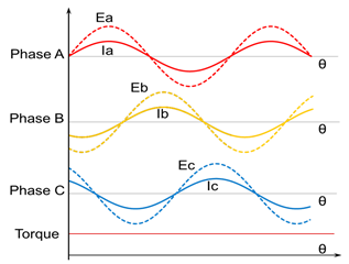
    In 180 degree commutation, FETs in the IPM switch continuously without any Hi-Z (floating) window, Below screenshot shows the Phase current and BEMF voltage of 180 deg commutation on a sinusoidal would BLDC motor.

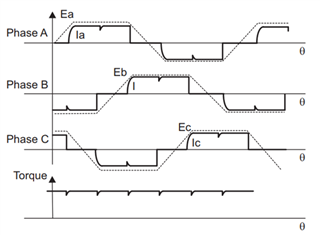
    In 120 degree commutation, there will be 60 deg window where the FETs will be Hi-Z ed. Below screenshot shows the Phase current and BEMF voltage of 120 deg commutation on a trapezoidal would BLDC motor.

    Input power in 180 deg commutation will be higher compared to 120 deg because the FETs conduct for a longer duration compared to 120 deg. However, the motor efficiency will be higher when driven using 180 deg commutation.  

    Regards,

    Vishnu