This thread has been locked.

If you have a related question, please click the "Ask a related question" button in the top right corner. The newly created question will be automatically linked to this question.

DRV8323: Clarification of TDRIVE State Machine

Part Number: DRV8323

Hi,

I've some question regarding the TDRIVE state machine. In the datasheets the gate current behavior is described as followed.

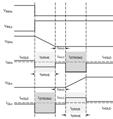
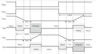
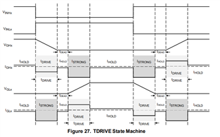
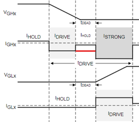
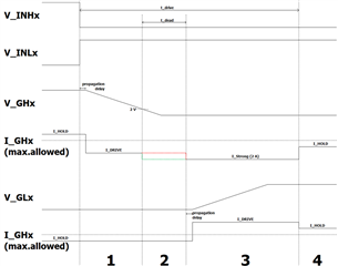
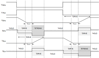
  • The driven current (highside) is applied until the gate-source voltage falls under the threshold (2V)
  • After reaching this threshold, the deadtime is injected and the hold current is applied to both (highside and lowside) FETs
  • When the deadtime is over, the lowside FET is driven by Idrive

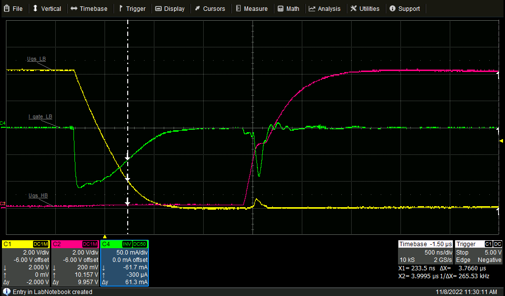
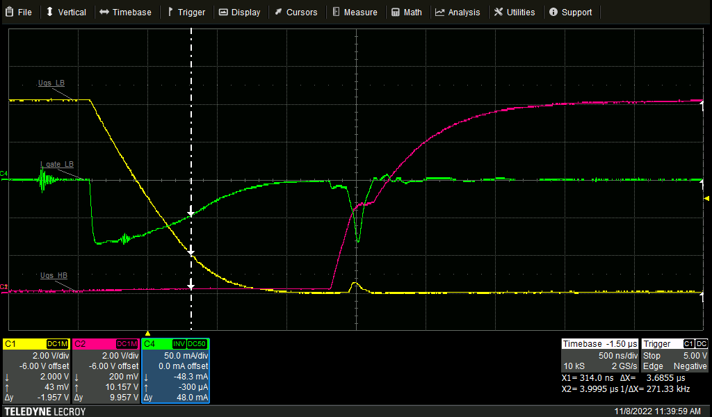
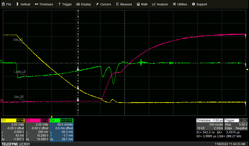
In my measurements I can observe a different behavior.

It seems like the driven current is also applied during the deadtime (between the cursors where U_gate-source_lowside is below the threshold of 2V). Should the driver reduce the current here to the IHOLD or is it intentional that the IDRIVEN is applied until the ISTRONG starts at the second cursor?

Can I expect a hard cut (e.g. within 20ns) from IDRIVEN to IHOLD when changing the TDRIVE states or is that a slow transition to the desired hold current?

C1: U_gate-source_lowside (yellow)
C2: U_gate-source_highside (red)
C3: phase current (blue)
C4: I_gate_lowside (green)

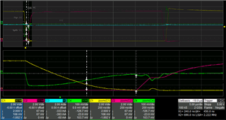
When switching on a FET, is there a threshold where the DRV detects a fully charged U_gate-source?
How does the TDRIVE state machine determines when the charge process is finished?

Thank you in advance for your help.

Kind regards

Tobias

  • Hi Tobias,

    Thanks for your question! I plan on taking a look at it in more detail and will aim to respond back to you hopefully by the end of the week.

    Regards,

    Anthony Lodi

  • Hi Tobias, 

    Regarding your last question about if there is a threshold where the DRV detects a fully charged U_gate-source, the answer to this is no, the TDRIVE state machine does not detect when the charge process is finished, it simply applies the ISTRONG and IDRIVE currents until the end of the tdrive time. The below updated TDRIVE diagram may be more clear:

    You mentioned that based on your measurements you observed that the DRIVE_N current is also applied during the deadtime. How are you measuring this current? What DRIVE_N setting are you using?

    Regards,

    Anthony Lodi

  • Hi Anthony,

    thank you for the adjusted TDRIVE diagram.

    The Measurements were taken with differential probes for both gate-source voltages.

    The gate current was measured across a 1 Ohm pre gate resistor of one of the two parallel low side FETs. A BNC Line direct soldered with one side to the pre gate resistors was used.

    The DRV deadtime in the measurement shown above was set to 400ns, the drive register high side 1737 (570mA drive, 660mA driven) and low side 1991 (570mA drive, 380mA driven).

    Kind regards,

    Tobias Widmann

  • Hi Anthony,

    regarding the updated TDRIVE diagram I got some additional questions.

    1. If there is no threshold for the end of TDRIVE, how do you determine if the gate is fully charged. What value is the mentioned threshold here?
        

    2. When using a software deadtime as in the picture below (e.g. 1000ns), where is the TDRIVE (4000ns) starting exactly. At the high side, the low side signal or is it starting from zero at each level change of a phase input signal?
        

    3. Comparing the old and your new TDRIVE diagram, it is noticeable that the ISTRONG section is missing when the associated FET is switched off. Is it right that there is just a IHOLD as shown in the new diagram?
         

    Kind regards,

    Tobias

  • Hi Tobias,

    I will aim to answer your other questions in more detail by early next week, but to answer your first question: A GDF will occur if the VGS voltage is not above approximately 2V by the end of the TDRIVE time. This is different than making sure the gate is fully charged. TDRIVE can be increased if necessary to give enough time for the gates to fully charge by the end of the TDRIVE time. A TDRIVE length must be selected to be long enough to cover the discharge of one FET + DEAD_TIME + time to fully charge the other FET. 

    Regards,

    Anthony Lodi

  • Hi Tobias,

    To follow up on your other questions (questions 2 and 3):

    2: When using software deadtime the TDRIVE time will reset at the toggle of an input. 

    3. The new diagram is correct: When a MOSFET is slewing on there is a possibility that the voltage slewing on the gate that is switching on can couple into the opposite MOSFET (that is supposed to be off), which could cause some parasitic shootthrough. This is primarily a concern for when a MOSFET is turning on (VGS voltage slewing up), so during this time a strong pulldown (ISTRONG) is used to hold the gate of the opposite MOSFET off. This isn't as much of a concern with a MOSFET slewing off, so no ISTRONG is used in that case.

    I am confirming with the team on the IHOLD current during the deadtime, I will get back to you once I have an answer.

    Regards,

    Anthony Lodi

  • Hi Tobias, 

    Sorry for the delay in getting back to you, I reached out to my coworker and he recommended increasing the deadtime so that we can see more clearly whether or not we get IHOLD during the deadtime. I would recommend using the max deadtime and retaking a waveform showing the voltage drop across the gate resistor, the GHx-SHx voltage, and the GLx to SLx voltage. 

    Regards,

    Anthony Lodi

  • Hi Anthony,

    in the attached measurements I've chosen a greater software deadtime. Furthermore I've repeated the measurements for three different sink current settings.

    sink current setting 380 mA 280 mA 160 mA

    Please keep in Mind, that two FETs are driven parallel.

    Kind regards

    Tobias

  • Hi Tobias,

    Thanks for the waveforms! Just wanted to confirm, when you say software deadtime are you meaning deadtime that is inserted by the MCU on the INHx and INLx signals? Or are you referring to programmed deadtime in the DEAD_TIME bits of the device registers in the gate driver? I would like to see a waveform where there is no deadtime inserted from the MCU but just relying on the deadtime of the DRV.

    Regards,

    Anthony Lodi

  • Hi Anthony,

    the first measurement (Oct, 18) was already taken with the maximum possible DRV deadtime of 400 ns.

    The latest measurements (Nov, 8) were taken with 400 ns DRV deadtime and ~1500 ns software deadtime, so as you assumed with delayed input signals.

    Regards,

    Tobias

  • Hi Tobias,

    I understand now, sounds good. Let me discuss this with my coworker and get back to you hopefully next week.

    Regards,

    Anthony Lodi

  • Comparing the old and your new TDRIVE diagram, it is noticeable that the ISTRONG section is missing when the associated FET is switched off.

    The new TDRIVE timing makes more sense than the old one: there is no reason for the already off lower FET to be driven further off during when the upper FET turning off, as there is a built-in body diode if needed for conducting the motor inductive current when upper FET turned off.

    n the attached measurements I've chosen a greater software deadtime. Furthermore I've repeated the measurements for three different sink current settings.

    sink current setting 380 mA 280 mA 160 mA

    The timing of these 3 pics show perfectly matching with the given new TDRIVE timing. I don't think we should expect that the gate current should have a sharp "step response" as no such timing in real life, at nano-seconds  time window.

    Brian

  • Hello Brian,

    I also do not really expect a sharp edge. Furthermore the measured behavior leads to a good switch off, even after reaching the 2 V threshold.

    The intention of my question is to understand, if the DRV is trying limit the sink current after reaching the threshold to the mentioned 50 mA or if the DRV continues the IDRIVE until the ISTRONG starts.

    Kind regards

    Tobias

  • The intention of my question is to understand, if the DRV is trying limit the sink current after reaching the threshold to the mentioned 50 mA or if the DRV continues the IDRIVE until the ISTRONG starts.

    Great question, Tobias. When we look at IGHx, programmable IDRIVE is applied during turning off the FET, to ensure GHx is low before the deadtime window. Why the design doesn't continue to keep IDRIVE during deadtime and then drive stronger with ISTRONG? I think during deadtime the system is electrically quiet and no reason for concern of having the upper FET to be accidentally switch to on again, so not continue to drive with IDRIVE for saving energy and reducing the generate heat on the chip. However, when GLx turning high, the lower FET turned on causing big spike on the system, especially the GND, and the noise could cause the upper FET to turn on, and so during this BIG BANG window, ISTRONG is applied to GHx to ensure it is off. 

    Brian

  • Hi Tobias,

    Wanted to provide a brief update: I am still trying to find confirmation regarding whether the gate driver switches to IHOLD during the deadtime period, I just reached out to a member of the design team to see if he knows. I will let you know once I get an answer.

    Regards,

    Anthony 

  • Hi Tobias, 

    I apologize for delaying in following up on this, I got some information from a coworker regarding IHOLD during deadtime a couple weeks ago, and I responded to him today asking some further clarifying questions. I will keep you updated once I get a firm answer.

    Regards,

    Anthony Lodi

  • Hello Anthony,

    thanks for the update and staying on the topic.

    Regards
    Tobias

  • Hi Tobias,

    Your welcome, I received further clarification on the issue but still had one remaining question that I asked for clarification for. Hopefully should have everything resolved by end of next week.

    Regards,

    Anthony Lodi

  • Hello Anthony,

    do you already have further information regarding the I_HOLD topic?

    Kind regards
    Tobias

  • Hi Tobias,

    Sorry for the delay in getting back to you on this. It does appear that IHOLD will only be used after tdrive has finished, so that will not generally be present during the tDEAD time unless tDEAD occurs after tdrive has ended. The fact that you saw IDRIVE continue during the tDEAD period is correct based on what I discussed with the designer. Sorry for taking so long to close this!

    Regards,

    Anthony Lodi

  • Hi Anthony,

    no problem. Thank you for helping with this topic.

    1. Is than the I_DRIVE (high side) kept until the driver starts at phase 3 to drive the low side (red) or how can I imagine this transition?
        

    2. Is this state machine correct or do I miss a relevant behavior?

    3. You mentioned that "unless tDEAD occurs after tdrive has ended". In which case can tDEAD occur after tDRIVE?

    Kind regards and looking forward to your answer,

    Tobias

    PS: as there are a few new points for the state diagram, is it possible to change the state machine also in the datasheet? I think the same point's are also relevant for DRV835x.

  • Hi Tobias,

    Let me consider this in more detail and aim to provide a response next week. 

    Regards,

    Anthony Lodi

  • Hi Tobias,

    Sorry for the delay in responding! 

    Questions 1 and 2: I have included an updated TDRIVE diagram below, showing the correct behavior. 

    3. tDEAD shouldn't generally occur after tdrive has ended unless the tdrive time is too short such that the gate doesn't cross the 2V threshold until around the end of tDRIVE. If it takes the entire tdrive time for the gate to shut off then there is a potential for tdead to occur after tdrive.

    We will look into updating the tdrive diagram in the datasheet in the future.

    Regards,

    Anthony Lodi