This thread has been locked.

If you have a related question, please click the "Ask a related question" button in the top right corner. The newly created question will be automatically linked to this question.

The delay between motor BEMF and Hall effect sensor output

Other Parts Discussed in Thread: DRV5013

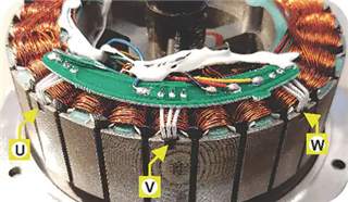
I have a BLDC motor with Hall effect sensor feedback. The Hall sensors are located in the center of every tooth of the motor (Figure 1) based on mechanical and electrical degree calculation.

I have looked over related BEMF signal vs the Hall sensor output. There is no drive section, only spun the motor by hand, not too fast.

As far as I know, for example, if you look at BEMFUV (U+,V-), you should see the switch from low to high or high to low in every zero crossing point.

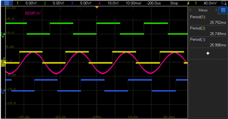
As you see, thoughthere is a significant delay between the Hall output and the BEMF zero crossing point. The periods of the Hall signals are the same. In every BEMF signal waveform, the same situation exists. (Figure 2)

Note: HALLU=Green, HALLV=Yellow, HALLW=Blue.

There is no offset in the Hall sensor placement for each 3 steps tooth of motor, centered placed.

What is the explanation for the delay between the Hall sensor output and the BEMF zero crossing point? How can I prevent this?

If the Hall sensors are not properly aligned we can use a delay function on microcontroller side. Is the delay normal or not?

  • The Hall sensors are located in the center of every tooth of the motor (Figure 1) 

    It is unusual to locate the sensors on the OD of the stator; most motors I worked with have the sensors located on the ID of the stator  and close to the magnet rotor. Maybe this is the reason why the Hall signals seem to be slightly leading the BEMF, not significantly through. 

    Can you rotate the motor in reverse of what you did and see of the same timing offset happens?

    In practice, the Hall sensors probably are triggered earlier than the BEMF as it is more sensitive to the magnetic field fringe than the stator coils.

    Also in this case, it is good to have the sensor signals timing in advance of the BEMF for better efficiency. If the timing offset is retarded then it is a more serious problem. 

    Brian

  • Hello Yardi,

    Thanks for posting to the MD forum! It is completely normal for hall sensors to have an output delay time, typically a manufacturer should specify this parameter in their datasheet. But since this is very difficult to measure it is usually calculated based on the delay time of the device itself. Just as an example here is the typical delay seen from a DRV5013 hall-effect latch:

    There are a couple of ways that users accommodate for this delay in their systems. You can physically position the sensor differently in your system essentially tuning out this delay with manual placement but the issue with this is that since the delay is fixed when you start spinning at a higher rate then this could reintroduce some unwanted delay in your system. The other way as you mentioned would be by using a delay function on the MCU, which is referred to as lead time adjustment. 

    In industry where high performance is of key importance, it is common for users to not use a delay at startup/slow speeds but as they speed their system up then they introduce the delay to tune the performance a bit better. Typically, these users are also tuning the physical position of the sensor as well to ensure they get good alignment at startup.

    Brian mentioned the position could be an issue since you placed in the outer diameter of the motor, but it looks like this motor is an outrunner type of BLDC motor so I think this should be fine, my only comment would be that typically we see the sensors out of the way of the armature since this is generating an magnetic field with the coils. You will usually see the sensor placed between the armature.

    Best,

    Isaac

  • When I rotate the motor in reverse direction, there is same timing offset.

    I am not sure that this situation is good or not. In some end product motors, I have seen no timing offset between BEMF and Hall outputs.

  • Hello Isaac,

    Actually, I have not mention about the sensor delay time. As you see, the delay exist between BEMF zero crossing point and related Hall effect output.

    Maybe, as you and Brian said position is not correct. How can I detect optimal position for the hall sensors? Is there any mathematical proof?

  • Hello Yardi,

    If the delay is fixed to me it seems like this points towards some sort of hall sensor delay. But it think altering the position of the sensor is a good place to start. 

    The position of the hall sensor placement can be calculated, you can refer to this post for more information: https://e2e.ti.com/support/motor-drivers-group/motor-drivers/f/motor-drivers-forum/365666/hall-sensor-arrangement-around-bldc-motor

    Best,

    Isaac

  • When I rotate the motor in reverse direction, there is same timing offset.

    I am not sure that this situation is good or not. In some end product motors, I have seen no timing offset between BEMF and Hall outputs.

    I agree that it seems the sensors are now located at the center of the stator poles, and so by shifting the sensor so that sensor signals aligned with the BEMF peak, then when motor runs in reverse direction then you will have the same timing offset issue.

    The sensor signal is leading the BEMF now, so it you rotate the motor backward, what would the sensor vs BEMF waveform looks like?

  • Maybe, as you and Brian said position is not correct. How can I detect optimal position for the hall sensors? Is there any mathematical proof?

    Please rotate the motor the other direction and post the new waveform.

    Brian