This thread has been locked.

If you have a related question, please click the "Ask a related question" button in the top right corner. The newly created question will be automatically linked to this question.

DRV8353RS-EVM: SPI query and programming of registers to select IDRIVE and CSA_GAIN

Part Number: DRV8353RS-EVM
Other Parts Discussed in Thread: TMS320F28379D, DRV8353, , C2000WARE, DRV8252

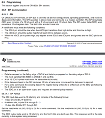
I know people do this, but as of yet I have not. I need to query and program some registers in the DRV8353 via the SPI port. For the EVM part I have a laptop serial port for doing this (CoolTerm) and for the 8353SRTAT part I am connected to a TMS320F28379D DSP using its SPI_A port and pins 27-30 of the DRV part. Please tell me (via way of examples) the format of the serial command to be used for query and for setting values (also to include baud rate, stop bits, data bits and parity. Ultimately I want to use a Matlab/ Simulink SPI module to perform the configuration.

Steve Abel

Configurable Controls

480.209.3344

  • Hi Steve, 

    Thanks for posting to e2e forum. I've assigned the thread to a team member for further support. 

    Regarding the SPI formatting, this information is in the datasheet for DRV8353 - https://www.ti.com/lit/ds/symlink/drv8350r.pdf

    Please see below snippets. 

    Best Regards,
    Andrew 

  • Andrew Liu. Thank you. The instructions were helpful and the figure as well. I have now monitored traffic on the four signals interface between my TMS3208F28379D (GPIO58-61) and DRV8353SRTAT (pins 27-30) [SDO, SDI, CLK, SCS]. Here is what I see good and bad. Chip select SCS looks just like Figure 54 going LO for the 16 clock cycles. CLK actually pulses downward 16 times, whereas the figure pulses HI. So far so good. The data from the TMS I have crafted in numerous ways. My MSB is a 1 (Hi) for READ on the left. The next 4 bits I have cycled from 0 to 7dec (1 = Hi). These I observe - see attachment for a sample. Early on I set the 11 data bits to zero. The return signal from the DRV is always Hi "FFFF" as read in a serial window or on the scope as pictured. I do not know whether the DRV is unable to send anything or if it is sending all 1s on purpose. It may be LOCKed at all 1s. I have tried sending W(0) for the first bit. I have also tried inverting 1s for 0s on the register address bits. I have tried sending various values for the data bits. But the return SDO signal never changes - always Hi. I expect SDO to tell me what is in the registers for a READ command (1), or tell me what I just wrote for a WRITE command (0). Any ideas how to proceed?

    YEL= CLK (16 down pulses at 10 MHz)

    VIO = SCS, STE 

    BLU = SDI   (R for 1 MSB, value 5 for address next 4bits, 0 data - as shown to finish 11 bits)

    GRN = SDO   always Hi

    C:\Users\steve\Desktop\CF_Photos\IMG_4762.jpg 

    Showing my connections to the DRV. SDO has 10k pull-up as shown, the others have 10k pull-down resistors

    C:\Users\steve\Desktop\CF_Photos\Circuit_TMS_DRV.jpg 

  • Hi  Andrew,

    I am helping the customer to attach these images. I am posting this in belalf of the customer(Steve)

    This is the continuation from first question above.

    C:\Users\steve\Desktop\CF_Photos\IMG_4762.jpg 

    C:\Users\steve\Desktop\CF_Photos\Circuit_TMS_DRV.jpg 

    Best regards,

    Jonathan

  • Hey Jonathan,

    I will aim to provide feedback before the end of the week.

    Best Regards,

    Akshay

  • Good news. I now see SDO output from the DRV board in response to SPI communication from the TMS320 board. I added a half cycle delay clock phase to improve capture window and more importantly set ENBLE to the DRV board to Hi (3p3v). I also see that default values in the 0h through 7h registers revert to defaults upon ENABLE going Lo. YEL = CSC, VIO = CLK, BLU = SDI with ADDR = 7h and R/W = 0, GRN = SDO. Can the LOCK bits be used to freeze the values?

    Steve

  • Hey Steve,

    I will aim to provide feedback before the end of the week.

    Best Regards,

    Akshay

  • I am still having trouble.

    As noted above I can now READ and WRITE from my TMS320F28379D Dev board to my DRV8353RS-EVM board, as long as ENABLE is Hi (to the DRV). Written data is lost when ENABLE goes Lo. I tried to overcome the revert to default register data by setting the 3h (address) b10 LOCK bit Hi. This bit refuses to go Hi and data cannot be locked in.

    I also have a more bothersome second issue. When attempting a READ and WRITE from a TMS320F28379D (same DSP) to a DRV8353SRTAT on a custom board I cannot write any data and in fact the data is always frozen at 0000hex. I verified the ENABLE pin is Hi. Is the default data on the DRV8353SRTAT supposed to be all 0000s? The default data on the DRV8353RSEVM is as follows (last 11 bits). Please help.

    '1000000000000000'
    '1000100000000000'
    '1001000000000000'
    '0001101111111111'
    '0010011111111111'
    '0010100101101101'
    '0011001010000011'
    '1011100000000000'

  • Hey Steve,

    I will aim to provide feedback before the end of the week.

    Best Regards,

    Akshay

  • Hey Steve,

    Just wanted to offer some information on the ENABLE pin.

    The ENABLE pin manages the state of the DRV835x family of devices. When the ENABLE pin is low, the device goes to a low-power sleep mode. In sleep mode, all gate drivers are disabled, all external MOSFETs are disabled, the VCP charge pump and VGLS regulator are disabled, the DVDD regulator is disabled, the sense amplifiers are disabled, and the SPI bus is disabled. In sleep mode all the device registers will reset to their default values. The tSLEEP time must elapse after a falling edge on the ENABLE pin before the device goes to sleep mode. The device comes out of sleep mode automatically if the ENABLE pin is pulled high.

    Will aim to review further and provide feedback.

    Best Regards,

    Akshay

  • The universal motor control lab is available in the current MCSDK, which can support LAUNCHXL-F280025C with DRV8353Rx-EVM. You may refer to the SPI configuration and control codes in this project which can be implemented on the other C2000 device includes TMS320F28379D.

    https://www.ti.com/tool/C2000WARE-MOTORCONTROL-SDK

    Example lab project at the folder: C:\ti\c2000\C2000Ware_MotorControl_SDK_<version>\solutions\universal_motorcontrol_lab\f28002x

    The SPI configuration codes can be found in HAL_setupSPI() in hal.c as below

    void HAL_setupSPI(HAL_MTR_Handle handle)
    {
    HAL_MTR_Obj *obj = (HAL_MTR_Obj *)handle;

    // Must put SPI into reset before configuring it
    SPI_disableModule(obj->spiHandle);

    // SPI configuration. Use a 500kHz SPICLK and 16-bit word size, 25MHz LSPCLK
    SPI_setConfig(obj->spiHandle, DEVICE_LSPCLK_FREQ, SPI_PROT_POL0PHA0,
    SPI_MODE_MASTER, 400000, 16);

    SPI_disableLoopback(obj->spiHandle);

    SPI_setEmulationMode(obj->spiHandle, SPI_EMULATION_FREE_RUN);

    SPI_enableFIFO(obj->spiHandle);
    SPI_setTxFifoTransmitDelay(obj->spiHandle, 0x04);

    SPI_clearInterruptStatus(obj->spiHandle, SPI_INT_TXFF);

    // Configuration complete. Enable the module.
    SPI_enableModule(obj->spiHandle);

    return;
    } // end of HAL_setupSPI() function

    DRV8353 read and write functions can be found in drv8353s.c file in this project.

  • I believe I have solved the issue. It seems to be a mechanical issue in that I have a cold solder joint between the CLK from the TMS320 and the DRV8252 input pin 29. When I jumper this with a copper shim the SDO comes to life. I am having a fresh board fabricated. This one is too difficult to rework. Thank you all for your input.

    Steve