Other Parts Discussed in Thread: DRV8350S-EVM, , DRV8353R, DRV8353
Hello,
For our battery-powered smoke extraction fans, we want to develop a brushless motor driver 1.5KW.
For a new development we want to use the reference DRV8350S.
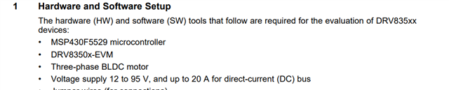
We plan to start our development work with the DRV8350S-EVM circuit board.
I have a problem with the start sequence, we use the firware SLVC755 sensorless withe the board DRV8350S-EVM.
The motor runs correctly without load.
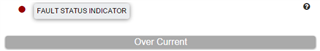
With the load (a propeller for a fan) I can't get the motor to start I have an overcurrent error.
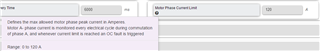
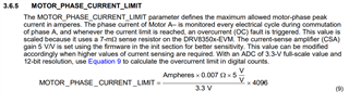
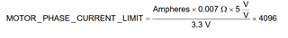
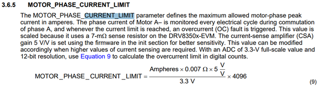
Which parameter is problematic ?
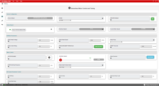
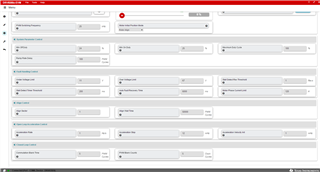
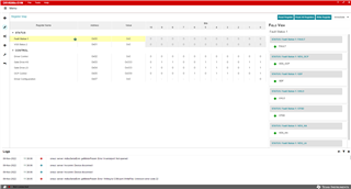
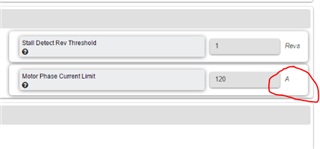
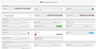
My configuration :
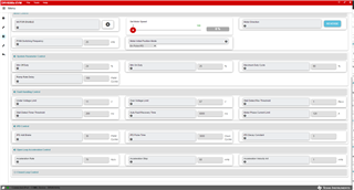
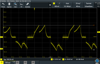
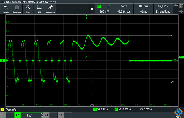
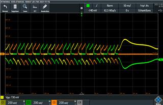
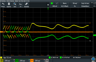
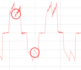
My result with the overcurrent error :
/cfs-file/__key/communityserver-discussions-components-files/38/20221020_5F00_165013.mp4
Thanks.for your help.