This thread has been locked.

If you have a related question, please click the "Ask a related question" button in the top right corner. The newly created question will be automatically linked to this question.

DRV8830 Stall condition - issues in the implementation

Other Parts Discussed in Thread: DRV8830, DRV8210
   
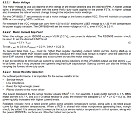
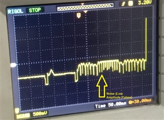
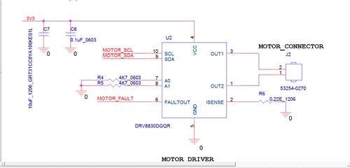
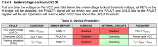
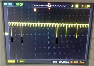
We are working on one project in which we have used DRV8830DGQR motor controller. As per datasheet when motor goes into stall condition, fault pin goes low and retains in low state till the fault condition is there. Practically while testing, we observed that it is giving pulse on fault pin. It does not retain in low state though motor is in stall condition. Also we are getting noise (low amplitude pulses) before getting the pulse on fault pin. It becomes difficult for host controller to sense the fault condition due to these multiple pulses.
  • Hey Shelake-san,

    Can you post an oscilloscope image of this happening?  Show VCC, nFAULT, OUTx voltage, and if you have a current probe show the current of the motor, or the voltage at ISENSE if you don't have a current probe.  

    It might be that undervoltage lockout (UVLO) is tripping and stopping the drive momentarily, then VCC recovers and re-enables the outputs, etc. very rapidly before the stall condition occurs.  

    Could you also give some more details on your system? - VCC voltage, current sense resistance, motor specs, etc.

    Regards,

    Jacob

  • Hey Shelake-san,

    If this is a new design, I recommend looking at the DRV8210 instead.  It is a much newer chip, supports 12V and 1.76A (vs DRV8830 7V 1A), uses 10x less current in sleep mode, is smaller, 1/3 the price, and we have a ton of them in stock.  

    Regards,

    Jacob

  • Hello,

        We have captured the pulse on the Fault pin, I am attaching the image.


  • Hey Shelake-san,

    We can't diagnose anything with just the nFAULT signal.  Please also post captures of VCC, OUTx, and the current of the motor.

    Also,   can you post your schematic?  I am wondering what your ISENSE resistor, bulk capacitance, and the A1 and A0 resistors are.

    Cheers,

    Jacob

  • Hello,

    I am sending you the requested waveforms for your reference, Please find below.

    1. VCC signal waveform:
    In normal motor operation, VCC voltage level are uniform, there is no fluctuation.
    If we tried to stall motor by putting external force, we are getting changes in the waveforms. Please find below image.


    2. Out x1 :
    In normal motor operation, Out X1 voltage remains high, there is no fluctuations.
    If we tried to stall motor by putting external force, we are getting changes in the waveforms. Please find below image.


    3. Out x2 :
    In normal motor operation, Out X2 voltage remains low, there is no fluctuations.
    If we tried to stall motor by putting external force, we are getting changes in the waveforms. Please find below image.


    4. Current consumption :
    In normal motor operation: 150mA.
    Stall Current: 240mA.
    RSense resistor used in the board is: 0.22OHM

    5. Please find below image schematic.

    Regards,

    Suraj.

  • Hey Suraj,

    It looks like during stall VM is dropping to approximately 2.4V.  According to 6.5 Electrical Characteristics, UVLO conditions occur below 2.47V. Higher bulk capacitance could potentially fix this issue, I would try 22uF or 47uF instead of 10uF.  

    So the device disables the H-Bridge and internal circuits, then VCC recovers to VCC > VUVLO, then the device tries to run again and the cycle repeats.

    This is occurring before the OCP trips.  With a 0.22Ω sense resistor the current trip point is 0.9A for OCP.  For your system since your stall current is around 220mA, you probably want a ILIMIT point more like 300mA.  This would need sense resistors of RISENSE = 0.2V / 0.3A = 0.66Ω using the same calculation as in 8.2.2.2 Motor Current Trip Point.  NOTE:  There's a typo in the datasheet, it should be "To set IILIMIT to 0.9 A, RISENSE" not 0.5A.  Maybe try this higher sense resistor value.

    Cheers,

    Jacob

  • Hi, We are more concerned about fault pin status. As you can see, Fault pin gives pulse when fault occurs. As per datasheet, when fault occurs, it should go to low and retain same logic unless we clear fault.

    Current behavior is - Fault pin goes to low, but doesn't remain at low

    Expected behavior is- Fault pin goes to low after detecting the fault, and retains same logic till we clear the fault

    This is as per my understanding.

    Thanks,

    Akshay

  • Hi Akshay,

    We are more concerned about fault pin status. As you can see, Fault pin gives pulse when fault occurs. As per datasheet, when fault occurs, it should go to low and retain same logic unless we clear fault.

    It is correct that for OCP case, the nFAULT will stay low until cleared by writing to the registers. But for UVLO case, the datasheet doesn't say the FAULT pin is latched low: "Operation will resume when VCC rises above the UVLO threshold."

    I also think the reason you have pulsing on the FAULT pin because the chip got to under voltage protection then VCC recovered to normal. To test this theory, please use 5A or higher power supply with short leads connected to the pcb, and importantly, add more cap to VCC -- just try with 470uF 5V, close to VCC and GND pins.

    Brian

  • Hey Akshay,

    Brian is correct - expected behavior for UVLO case is that fault pin clears (goes back high) once VCC rises above UVLO threshold.

    Please test with more bulk capacitance, we are fairly confident this is a UVLO fault not OCP fault occurring and clearing.

    Best,

    Jacob

  • Hey Akshay,

    Were you able to solve your issue, or are you still working on it?  If solved, I will close this thread soon.

    Regards,

    Jacob

  • Hi Jacob,

    This issue is not resolved.

    As motor is not stopping automatically in jam condition, I am checking fault pin interrupt. When UVLO fault occurs, interrupt gets generated and I am stopping the motor in my SW.

    It works pretty well and solves our requirement(Motor has to stop during jam condition) when using external power supply(6V).

    If I change power supply from External adapter to Battery(4V). UVLO condition is detected too early and motor stops.

    We have to have OCP detection pulse instead of UVLO.

    Thanks,

    Akshay. 

  • Hey Akshay, 

    What changes have you implemented since we last talked?  Did you try the higher bulk capacitance?  I see higher voltage fixes it, but yeah you need it to run on battery power of course.  

    Regards,

    Jacob

  • Hi Jacob,

    We have tested with 470uF. Whenever I try to stall motor, I always get UVLO fault instead of OCP/Ilimit fault.

    Regards,

    Akshay

  • Hi Suraj,

    4. Current consumption :
    In normal motor operation: 150mA.
    Stall Current: 240mA.
    RSense resistor used in the board is: 0.22OHM

    If the desired stall current is 240mA, then the Rsense should be 0.83 Ohms instead of 0.22 as you current have. This is why during motor stall, the high load current pulled the supply voltage down too low and triggered the UVLO fault.

    It works pretty well and solves our requirement(Motor has to stop during jam condition) when using external power supply(6V).

    If I change power supply from External adapter to Battery(4V). UVLO condition is detected too early and motor stops.

    We have to have OCP detection pulse instead of UVLO.

    Because the 4v batt has higher internal resistance, and so it drops more voltage causing UVLO whenever the motor is stalled. You need to select Rsense with a proper value so the driver can detect the stall current and trigger the FAULT output to interrupt the MCU.

    We have tested with 470uF. Whenever I try to stall motor, I always get UVLO fault instead of OCP/Ilimit fault.

    You cannot rely on OCP to stop the motor in this case, as OCP threshold is 3A worst case and your motor will never can cause this high current. Use the Rsense current limit as I wrote above.

  • Hey Akshay, sorry for the delay.

    I recommend following Brian's advice above of trying a different Rsense resistor.  Try 0.8 ohms (could put 4 of your 0.22ohms in series) or 1.0 ohms and see if it works like you want it to.  

    Regards,

    Jacob