This thread has been locked.

If you have a related question, please click the "Ask a related question" button in the top right corner. The newly created question will be automatically linked to this question.

DRV8243-Q1: whether Register only control is feasible?

Part Number: DRV8243-Q1

Dear team,

My customer hopes to use Register only control method to drive BDC. According to below description, I think it is feasible, and the register only control method can achieve the exactly same function with pin only control method, right? If they use this method, they can float IN1, IN2 and DRVOFF pins, right? Is there any risks here?

In addition, how to connect nFault pin if not used?

Thanks & Best Regards,

Sherry

  • Hi Sherry,

    Thank you for your question. It is possible and works fine if no PWM operation.

    If PWM operation and PWM frequency is faster (e.g 20KHz), SPI communication delay makes less accuracy of PWM frequency and duty cycle.

    regards

    Shinya Morita

  • Hi Shinya,

    Thanks for your reply!

    Currently they plan to use 10kHz PWM frequency, is it ok?

    In addition, you don't answer some questions. How to connect IN1, IN2 and DRVOFF if the customer just use register only control? Float?

    Thanks & Best Regards,

    Sherry

  • Hi Sherry,

    10KHz is not slow I think but it is customer's decision. 10KHz PWM should have two toggle in 100us. Each SPI comment is ~2us period with 10MHz clock. MCU mush keep sending at least two command in 100us.

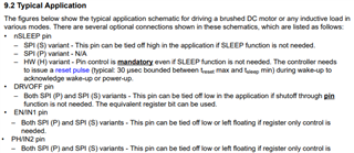
    These pins can be floated. Please refer datasheet 9.2

    regards

    Shinya Morita

  • Hi Shinya,

    Thanks for your reply! But I don't understand below description. Could you please help clarify it? In my understanding, if PWM frequency is 20kHz, then MCU must keep sending at least two command in 50us which is more strict. 

    10KHz PWM should have two toggle in 100us. Each SPI comment is ~2us period with 10MHz clock. MCU mush keep sending at least two command in 100us.

    Why this delay will impact the PWM frequency and duty cycle? For example, 10KHz PWM should have two toggle in 100us, and duty cycle is 50%. Each toggle needs to add 2us SPI command time, so high time of PWM will be 48us+2us, and low time of PWM is 48us, so the PWM frequency and duty cycle is changed, right? If so, the higher the frequency, the lower the accuracy. Because if PWM frequency is 20kHz,  the high time is 23us+2us and the low time is 23us.

    SPI communication delay makes less accuracy of PWM frequency and duty cycle.

    Thanks & Best Regards,

    Sherry

  • Hi Shinya,

    Can you give me the reply today? Thanks!

    Thanks & Best Regards,

    Sherry

  • Sherry,

    Morita-san is out of the office on travel.  

    Your understanding is correct and I think you understand the delays do to SPI write time.  These delays won't always be fixed and could result in some jitter on the edges of the PWM.  If this is acceptable to the customer, than the method can work.  Also, customer needs to understand that accuracy will be degraded in terms of minimum and maximum PWM duty cycle.  With 2us per command, a low pulse <2us won't be possible.  

    Regards,

    Ryan

  • Hi Sherry,

    My customer hopes to use Register only control method to drive BDC. According to below description, I think it is feasible, and the register only control method can achieve the exactly same function with pin only control method, right? If they use this method, they can float IN1, IN2 and DRVOFF pins, right? Is there any risks here?

    In addition, how to connect nFault pin if not used?

    I think it depends on the application of the motor control -- simple like running a fan or high performance like 10bit pwm servo control.

    I would only use SPI_pin control  for S_EN_IN1, S_PH_IN2 only for simple motor application as it requires the host processor to write twice to the SPI_IN register per every pwm cycle. Imagine for a typical servo closed-loop control, I would use 10bit PWM and 20Khz pwm, then every the host needs to write 2 times every 50us to the SPI_IN. This doesn't sound too bad, but consider this worst case: the PID control loop needs to output a pwm value of 1 (100% is 0x3FF for 10bit pwm), so the host first write the bit to 1 at time t1, then it needs to toggle the bit to zero at t2, which is 97ns after t1. The host needs to run a Timer counter interrupt every 97ns to trigger a SPI write. Do you want to do this?

    I don't know why TI engineers didn't add a PWM register for the SPI version, either 10bit or 8bit register, then the driver chip just has an internal pwm generator taking the 8bit or 10bit input via the SPI. This helps off load the host from writing the SPI_bit .

    Yes, IN1, IN2 and DRVOFF can be float as they have internal pull up or pull down.

    Since nFault is an output, you don't need to do anything if you want to read the nFault status using SPI.

    Brian

  • Hi Ryan,

    If my understanding is correct, then below description is wrong. The higher the frequency, the lower the accuracy, then 10kHz is more accurate than 20kHz., is it correct?

    If PWM operation and PWM frequency is faster (e.g 20KHz), SPI communication delay makes less accuracy of PWM frequency and duty cycle.

    Thanks & Best Regards,

    Sherry

  • Sherry,

    You are correct.

    If frequency is lower, like 10KHz, then the SPI communication delay will have less of an impact on min/max duty cycle as the period is longer with 10kHz vs. 20kHz.  So if a customer wants to operate in this manner, than lower frequency would be preferred. 

    All of Brian's points are also valid.  SPI control is really meant for simple ON/OFF control of a bridge.  

    Regards,

    Ryan

  • Hi Sherry,

    If my understanding is correct, then below description is wrong. The higher the frequency, the lower the accuracy, then 10kHz is more accurate than 20kHz., is it correct?

    Keep in mind that 10Khz is in the human audible hearing range, and for some motors it could cause the audible noise. 

    Brian 

  • Hi Brian,

    I am not very clear about below clarification. How does 97ns come from? Is it included into 2us SPI command replay?

    but consider this worst case: the PID control loop needs to output a pwm value of 1 (100% is 0x3FF for 10bit pwm), so the host first write the bit to 1 at time t1, then it needs to toggle the bit to zero at t2, which is 97ns after t1. The host needs to run a Timer counter interrupt every 97ns to trigger a SPI write. Do you want to do this?

    Thanks & Best Regards,

    Sherry

  • Hi Sherry,

    I am not very clear about below clarification. How does 97ns come from? Is it included into 2us SPI command replay?

    It comes from the calculation for an example that if I am going to use a 10bit PWM (for better resolution and less system gain as compare to 8bit or less PWM) for a servo position closed-loop control with PID digital filter, with 20Khz pwm as I don't want to have the audible noise when using lower pwm frequency (human can hear up to 20Khz noise). So with 20khz pwm and 10bit resolution, each pwm step is:

    (1/20khz)/1024 = 49ns, not 97ns as I wrote before. So the MCP writes to the spi to set the pwm bit to 1 at time t0, then 49ns later the MCP has to toggle the spi bit to zero at t1, then 50us after t0, MCU toggle the spi bit to high again to start a new pwm cycle. For a value of 50% duty cycle, then MCU writes at t0 to set the spi bit high, then 25us late at t1 MCU toggles the bit low. This takes a lot of MCP processing power just to create the correct pwm signal using SPI interface. Therefore, it is better for MCU to output pwm signal to drive the INx pin directly, as most MCU can easily generate 10bit pwm by writing to a pwm value register.

    Brian