This thread has been locked.

If you have a related question, please click the "Ask a related question" button in the top right corner. The newly created question will be automatically linked to this question.

DRV8434A: Trq-Cnt reporting stall even when motor is not stalled.

Part Number: DRV8434A

Hello,

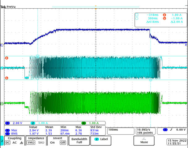
We are using DRV8434A stepper motor driver for our application. For stall monitoring, we are using the driver in Torque count mode. Our external MCU is monitoring the analog voltage at TRQ_CNT/STL_TH pin for stall detection. We are running the motor at 50kHz (STEP input). Microstepping mode is 1/8th step. We have set the ENABLE pin to Hi-Z to enable 8x torque count scaling. The voltage at VREF pin is set to 1.2V.

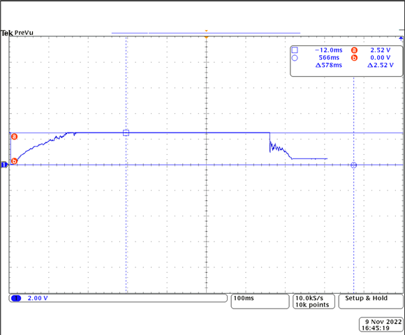
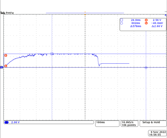
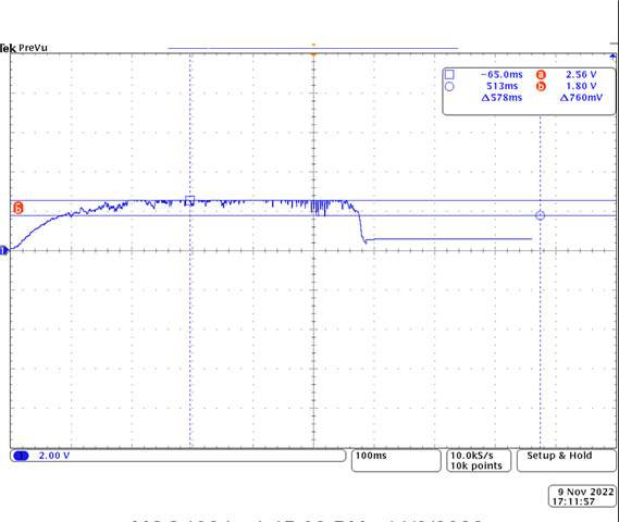
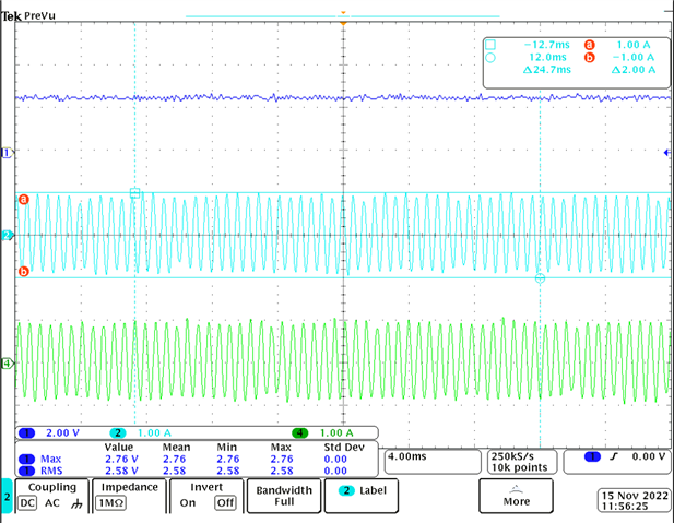
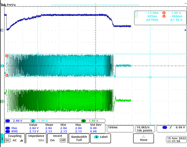
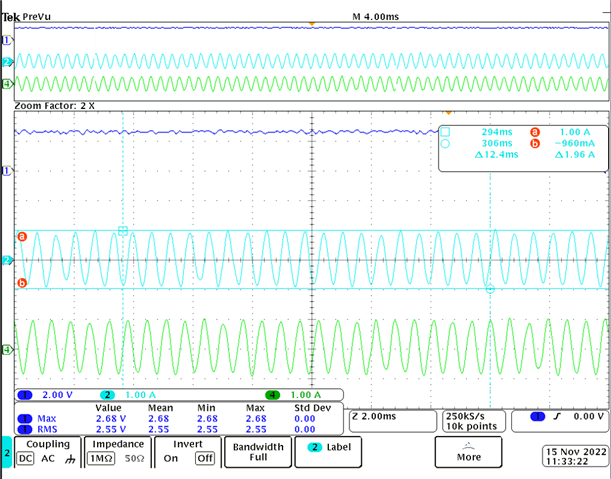
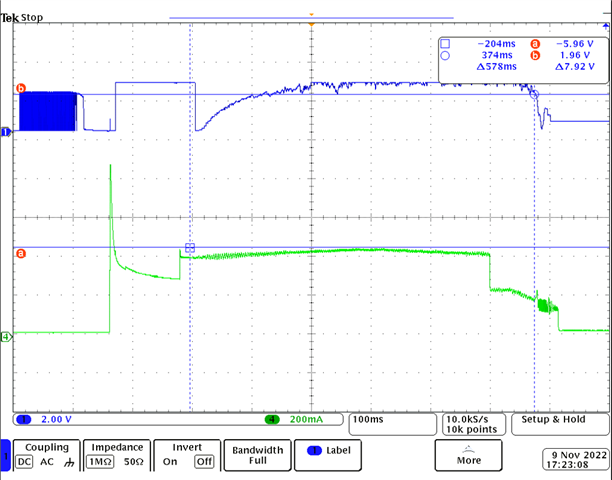
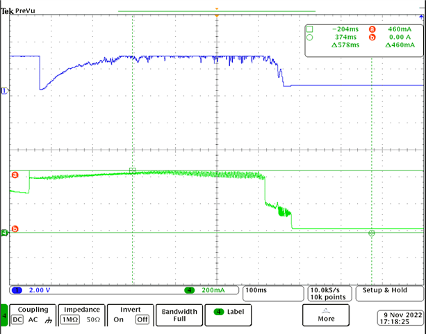
When the motor runs normally without any stall, we see the TRQ-CNT pin give around 2.5V. When the motor stalls, we see a dip in TRQ-CNT. We have set 1.8V as the threshold in our mcu to determine if motor is stalled or not. With this algorithm we are able to detect stall in one type of motor(make 1).

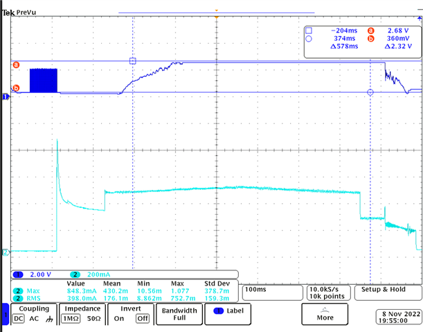
In another motor(make 2 , from a different manufacturer) using the same algorithm, some times we are seeing the TRQ-CNT dip even when the motor is not stalled. The TRQ-CNT is dipping below 1.5V, even when the motor is running freely. This is giving us false positive stall alert.

Stall detection is happening perfectly in make 1 kind of motors. But in make 2 motors we are seeing this issue.

Could you please help us in understanding what might be causing this and help us find a solution for this?

Thank you!

  • Hi,

    TRQ-CNT is affected by the stepper motor winding resistance and inductance so it is possible for two different makes of motors have different TRQ-CNT under the same operating conditions. The stall threshold will be different for the motor make 2 in this case, which should be lower than the TRQ-CNT output when the motor is running freely. Usually lower winding resistance produces higher TRQ-CNT value when compared to a high winding resistance stepper motor.

    Regards, Murugavel

  • Hi,

    Please find the motor inductance and resistance below,

    Motor Resistance Inductance
    Make 1 1.9 Ohms 0.5mH
    Make 2(with stall issue) 1.9 Ohms 0.8mH

    The image below shows the TRQ-CNT pin voltage when the make 1 motor is running freely.

    In the beginning and end we are seeing a rise and fall in TRQ-CNT because of our acceleration and deceleration profiles. I am not detecting stall in these regions. I am detecting stall once the TRQ-CNT voltage stabiles to 2.5V. Now if the TRQ-CNT falls below 1.8V, I am considering it as stall. This algorithm works fine for stall detection in make 1 motor.

    The images below shows the TRQ-CNT pin voltage when the make 2 motor is running freely.

    In the above image, I dont see any abnormalities in TRQ-CNT and the run was not detected to be stalled.

    When running the same motor again, sometimes we see a TRQ-CNT profile something like below.

    Here we saw the TRQ-CNT dip, even though there was not load on the motor. Both the 2nd and 3rd image were captured on the same motor under same conditions. 

    Sometimes I have observed the TRQ-CNT dip to even below 1V when there was not load on the motor. 

    We wanted to know what is causing the TRQ-CNT to dip even when there is no load. 

    We are getting a lot of false positive stall detections due to this.

    Thanks.

  • Hi,

    Thanks for the details. This helps us understand your question better. Have you tried multiple motor make 2 units and observed similar behavior? This appears like an mechanical friction related issue with the motor. Is this a bare motor or is it in an axis drive type of mechanism with no load condition?

    Thanks, Murugavel  

  • We do not believe the problem to be friction related since we have seen this issue when the motor was made to run in its free state i.e. nothing connected to the motor. The motor was made to run without stall detection at very low current to help identify any friction related issues and it ran without issue. We also tested with a new motor in free state and we continue to see this issue.

  • Hi,

    Thanks for getting back. In order to get stable TRQ_CNT the current regulation must be consistent for every microstep. TRQ_CNT is computed from TOFF values of the current regulation. What is the supply voltage used for motor 1 and 2? We would like to review the current waveforms for both steppers at the target speed. Please send us the current waveform for both make 1 and 2 motors.

    Regards, Murugavel 

  • Hi,

    Could you please send us scope shots of the current waveforms for both steppers make 1 and 2 at the same target speed in question? Thanks.

    Regards, Murugavel  

  • Yes. Will send the waveforms in some time. Sorry for the delay since I was on vacation.

  • Hi,

    Please find the waveforms below. 

    Make 1 Motor:

    Channel 1 is TRQ-CNT, Channel 2 and 4 are current through the 2 motor coils.

    Channel 1- TRQ-CNT, Channel 2 - System total input current

    Make 2 motor:

    Channel 1 is TRQ-CNT, Channel 2 and 4 are current through the 2 motor coils.

    Channel 1- TRQ-CNT, Channel 4 - System total input current

    Please let me know if you need anything else.

    Thank you.

  • Hi,

    Thank you for capturing and sending us these waveforms. Unfortunately I'm unable to judge if the current regulation is happening as desired at the microstep level. I'd like to have the current waveforms with more detail. Below is an example. Would be even better if further scaled up like to full screen scale showing one or two full cycles peak to peak with each microstep having enough information to show the current regulation ripples. I did notice the current waveform peaks are not stable. Is the VM voltage stable and with minimum ripple while the motor is running at the target speed? There seem to be occasional dips in current waveform peak-to-peak values especially with the motor 2. 

    Regards, Murugavel

  • Hi,

    Here is the better waveform of make 1 motor current:

    Make 2 motor:

    I am using a constant power supply of 24V as supply voltage. The same power supply was used when running make 1 and make 2 motors.

    Thank you.

  • Hi,

    Thank you for providing these waveforms. We will review these in detail and get back to you. Are you based in Bangalore, India?  

    Regards, Murugavel 

  • Thank you. Yes, I am based in Bangalore, India.

  • Hi,

    We reviewed the waveforms and unable to find anything unusual electrically. We have seen in the past some stepper motors result with noisy torque counts based on the mechanical precision of the poles construction. We wanted to rule out electrical issues by looking at the comparative parameters and the current waveforms, appreciate you providing us all those details. It appears the noise is likely due to the mechanical properties of motor 2. One suggestion we have is to use an RC low pass filter to smooth out the noise on this torque count output. Alternately you could also implement a moving average filter in the MCU on the ADC converted digital samples of the torque count, like a 32, 64 or 128 samples moving average. This would result in a smoother profile of the torque count regardless of the noise. Having an RC filter would be the easiest to manage but would require hardware change. A firmware moving average filter would not require any hardware modification. Thanks.  

    Regards, Murugavel 

  • Hi,

    Thank you for providing these solutions. We will try them out.

    Thanks!

  • Hi,

    Thank you. I'm closing this thread.

    Regards, Murugavel

  • Hi,

    Could you please suggest the values for the RC filter that would be suitable for our needs mentioned above?

    Thank you.

  • Hello!

    It really depends on what cutoff frequency you desire for the filter.  Plugging this in to a calculator like found below will give you the component values.  

    https://www.digikey.com/en/resources/conversion-calculators/conversion-calculator-low-pass-and-high-pass-filter

    Regards,

    Ryan