This thread has been locked.

If you have a related question, please click the "Ask a related question" button in the top right corner. The newly created question will be automatically linked to this question.

MCT8316Z: Request Help to Reduce Ripple on the Rotational Speed at Low RPM settings

Part Number: MCT8316Z

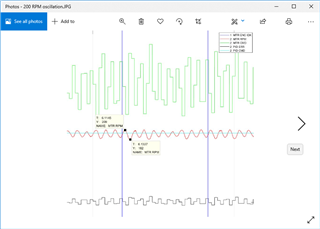
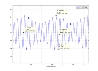
We are using the MCT8316Z controller to drive a small motor from 200RPM up to 6000RPM. The requirement for the control loop is to adjust the PWM into the MCT8316Z to run at a fixed rotational speed that is determined by various system parameters. At low speeds (say 200RPM) we have observed higher than expected variations in the rotational speed even when we run in open loop mode with a fixed PWM setting. There is about +/-5% variation that has a frequency that is a multiple of the rotational speed. The plot below shows the control loop attempting to smooth out the ripple, but really is not able to have any effect at that frequency. I would like help to if there are any of the strap settings for the controller that would be recommended to improve the performance.

  • Hi Randy,

    The plot below shows the control loop attempting to smooth out the ripple, but really is not able to have any effect at that frequency.

    There are 3 waveforms on the pic, without any introduction, I have no idea what they are. Is the middle one the motor speed?

    Brian

  • Do you use FGOUT for speed feedback -- what is the value for FGOUT_SEL? Or do you use encoder?

    At 200rpm or 3.3 rev per second is fairly slow speed, and so it is more challenge to control it at precise speed, and it all depends on the gain setting for P and I in the PID loop. How do you measure the speed feedback -- frequency or period of the pulses?

    P.S. How many pole-pair for the motor? High poles will give high FGOUT resolution for better speed control.

    At low speed, measured period is better than measured frequency for speed feedback.

    Brian

  • Hi Brian, 

    The control loop uses optical encoders with 242 encoder stripes per revolution. The plot shown has a legend but is hard to see - the RPM is the red waveform that has the more sinusoidal looking ripple waveform about 200RPM. The motor is a Maxon EC 20 series 5 watt BLDC device with 4 pole pairs.

  • Hi Randy,

    here is about +/-5% variation that has a frequency that is a multiple of the rotational speed.

    This sounds like you don't have enough gain in PID. What happened when increase more gain?

    242 encoder lines seems odd; a custom encoder? How do you measure the motor speed? Reading delta quadrature encoder counts per delta time, or measure the encoder pulse period? Do you use quadrature counts or just counting pulses?

    Brian

  • HI Brian,

    The optical encoder is custom. The motor speed is calculated by counting optical encoder counts and dividing by time. We do use quadrature counts so that we actually have 968 counts per revolution. A bit of effort has gone into trying to change the control loop P and I coefficients to get it to try to dampen out the ripple. So far, this has not significantly improved things. Note that we also have a dual range Motor Voltage. At low speed (less than 600RPM), we select 5V for the Motor Power and at higher speeds (> 600RPM), the Motor Voltage is set to 14V. 

  • Hi Randy,

    So 5% speed error is not acceptable. What is your spec on the speed? Instantaneous and accumulated error?

    Brian

  • Hi Brian,

    The motor is a facet optical wheel that directs small laser dots onto a skin surface. The good news is that the fine pitched optical encoder allows for the laser to be able to fire at the correct location on the wheel. We calculate the width of the laser fire pulse based on the nominal wheel speed that is set. At the plus peak in Motor RPM, the available facet time is 5% less than expected and we can start to bump into the edges of the facets with the laser beam. The control loop does a good job of keeping the average speed very accurate (within 1% or so), but we would like the ripple to be as small as possible. We had a legacy product that actually did a better job than this at providing low ripple over full range (200RPM to 6000RPM), but the controller is end of life and the motor had a higher number of poles that most likely helped out. We may be able to live with +/-5% if we cannot do better, but would like to see what else can be done.

  • To have the best speed control, you might want to think about doing phase-lock-loop instead of encoder counting.

    Say at 200 rpm, you want to lock the shaft encoder signal to a synthesized clock of 200/60*242 = 806.67 hz; the 806 integer is easy for a counter, and the fraction 67/100 can be done with the clock pulse dithering faster 6 times and slower 10 times.

    A timer counter can be used to measure the phase error between the clock edge and the encoder edge, then use PID to keep the phase error to either zero or a constant. Then you have the motor locked to the generated clock -- very precise.

    Brian

  • The motor speed is calculated by counting optical encoder counts and dividing by time.

    What is the speed sampling time? 

    Brian

  • We can set the update rate for the RPM calculator. Right now, we are using 800Hz.

  • We can set the update rate for the RPM calculator. Right now, we are using 800Hz.

    So the motor speed is 200/60*242*4/800 = 4 counts per sample. So the speed error resolution is too coarse - one out of 4 or 25% variation on the pwm output , which could cause the speed oscillation as you had observed. Slow down the sampling time to 200hz will improve the speed measurement by 4x. This method is OK for high motor speed, but I think measure the encoder period is better (less error) for slow speed. 

    Brian 

  • Thank you for the suggestion - I will give this a try.

  • Hi Brian,

    One experiment was to add about 60 grams of extra weight to the wheel (currently only 10grams). This resulted in a significant reduction in the ripple. I think our relatively low rotational inertia causes a significant amount of ripple as the windings pass by each of the poles (ie back emf). We cannot easily add so much extra weight to the wheel to fix this, but was a helpful insight. The next approach would be to see if we can speed up the response of the MCT8316 forcing function as it receives a commanded change in the input PWM. The ripple frequency is only 30hz - probably would want the control loop to be able to respond within a millisecond or so to be able to dampen out the ripple. I have attached schematic and better plot of ripple - can I speed up response by reducing capacitor on ILIM pin?

  • can I speed up response by reducing capacitor on ILIM pin?

    No. The cap is a filter for the voltage divider to set the current limit -- a DC level; it has nothing to do with the motor response to PWM change.

    Yes, you can add more inertia to the load for better stability, but higher inertia load will slow down the motor response too, such as when you want to change motor speed.

    As I said before, using encoder count per delta time -- 4 counts at 200 rpm -- will have too much error in the speed measurement -- 25% error in this case due to quantized error. I suggest to measure the encoder pulses period with timer-counter and having very small error because the counter clk frequency is very high -- MHZ in this case. I believe the ripple is caused by the measured motor speed bouncing between 4 and 3.

    Brian

  • Hi Brian,

    It turns out that even though there are only 242 optical strips, the reader provides quadrature outputs so that we end up with 968 counts per revolution of resolution. At 200RPM, we end up with 16.1 quadrature counts per 200Hz sampling interval so that +/-1 count would be about +/-7.5% error. The +/-7.5% error is certainly problematic and could explain the artifact. However, adding the 66 gram weight in that case should not have made any difference. 

  • Brian,

    One more bit of information is that the RPM calculator is different than I had understood previously. It turns out that our system counts 100Mhz clock tics per each encoder transition. The resolution of rotational speed is actually a small fraction of 1RPM at 200RPM. 

  • It turns out that even though there are only 242 optical strips, the reader provides quadrature outputs so that we end up with 968 counts per revolution of resolution. At 200RPM, we end up with 16.1 quadrature counts per 200Hz sampling interval

    Previous post you said 800Hz speed measure sampling time, and this is why I wrote 4 counts per sample.

    7.5% speed error is still too big when compare to period measure speed method, which depends on the clk. Example: at 100Mhz counter clk, the period of the encoder is: 

    At 200rpm, encoder frequency is 806.7 hz; the period counted by the counter is 100Mhz / 806.7 = 123961, with 1 count error or 0.0008% error, better than 7.5% error.

    Brian

    One more bit of information is that the RPM calculator is different than I had understood previously. It turns out that our system counts 100Mhz clock tics per each encoder transition. The resolution of rotational speed is actually a small fraction of 1RPM at 200RPM. 

    The 100Mhz clk for the encoder counter has nothing to do with the encoder count resolution which is defined by 242x4 per revolution, regardless the clock tick.

  • Sorry for the errant information. The 800Hz update rate is correct, but they do not calculate RPM by dividing encoder counts per fixed time interval. Instead the RPM calculator measures the amount of elapsed time (in 100Mhz tics) per each encoder count and provides some filtering so that RPM updates at 800Hz have a much better resolution than if we measured just the number of encoder counts in a fixed 800Hz sampling time period. 

    Anyway, the artifact is not caused by optical encoder resolution - the experiment of adding mass to the wheel supports this assertion. Given that we are not likely to be able to add significant mass as a solution, I think the only solution would be to make the MCT8316 be able to make the motor respond fairly quickly to changes in the PWM input or possibly going to a motor with more poles or something like that. 

  • Instead the RPM calculator measures the amount of elapsed time (in 100Mhz tics) per each encoder count

    Wait, so now you say the motor speed is the number of clk ticks per each encoder count? Then how do you get only 16 counts?

    Please, what is the 200rpm motor speed that the processor calculated? 16 or something else?

    If the speed is the number of clk ticks per encoder count (not encoder signal pulse), then how do you get this 242x4 hz signal to trigger the counter capture function?

    Brian

  • Brian,

    Thanks for all your inputs.

    Randy,

    Please let us know if there is any further assistance needed.

    Regards,

    Vishnu