Hello TI team
I am working on MCF8316AEVM. The board and motor was configured and tested with the analog potentiometer. Then the input is configured to accept PWM (duty cycle) at 10 to 325Hz.
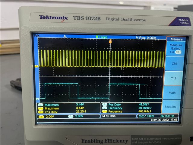
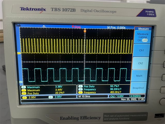
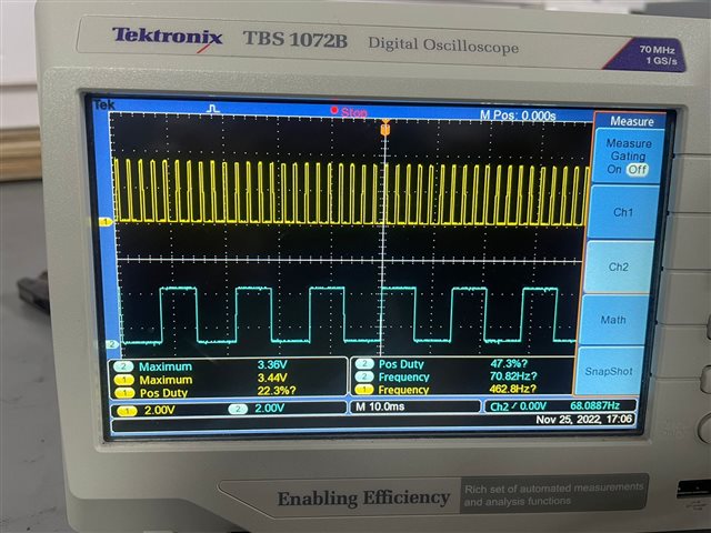
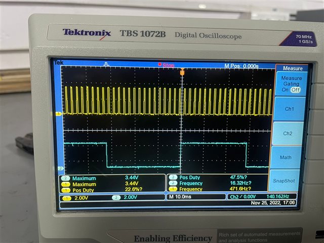
I gave PWM from RaspberyPi which is 3.3V at 50Hz. Whenever input pwm is provided at any particular dutycycle, the motor starts spinning with some jerks and then speed starts varying and later it stops.
After a moment it restarts the same behaviour. The EVM is not able to spin the motor at the requested speed.
Can you suggest why the motor behavior is like this?
Thanking you
K Bindu