Other Parts Discussed in Thread: DRV8962, SN74HC125
Hello TI Team,
I will be using DRV8412 (potentially DRV8432) to drive Brushed 24V DC motors in a bi-directiona manner.. I am confused about topics listed below and I will appreciate your support.
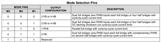
1) I will be driving two DC motors bi-directionally. So, natural operation mode of the device is Dual Full Bridge Mode (M3=0, M2=1, M1=1). According to the datasheet, in this mode,complement of the control signal (PWM_A) of half-bridge A is fed to other half bridge B. In this case, is bi-directional operation possible? How can one apply brakes? I think this mode is only suitable for full speed (100% duty cylce) opreation. Am I correct?
2) I had a closer look at the first typical application (section 8.2.1). In the design parameters (Table 3.), operation mode is said to be parallel full bridge. I believe that it is not the case for this typical application. Are there any typo? Also in the schematic in the typical application all mode selection inputs (MX) are set to 0.
3) Should I use the first operation mode (M2=0, M1=0) rather than fourth operation mode (M1=1, M2=1)? Because I believe that in this case, one has full control over H-bridge (two control signals for each H bridge). Though, I wondered if I can use the latter operation mode or not.
Sincerely,
Burak Keskin