This thread has been locked.

If you have a related question, please click the "Ask a related question" button in the top right corner. The newly created question will be automatically linked to this question.

DRV8305: noise issue

Part Number: DRV8305

Hi team,

Here's an issue from the customer may need your help:

The customer uses an open source project's F28069M Evaluation Board+8305 scheme to control the motor, the firmware is also provided in the original project, and the motor runs smoothly and without noise.This project was followed by the design of an integrated PCB board, known as Micro driver, using the F28069M chip + 8305, which is currently the V2 version.

The same firmware and algorithm are used by the customer to entrust the PCB patch manufacturer with the circuit diagram, and the motor makes a sharp noise and is stuck. As shown in the following video:

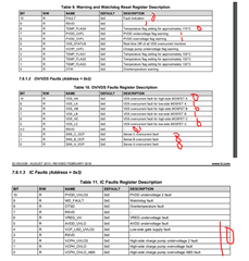
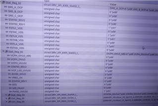
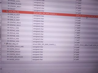
Read back the status of the 8305 through SPI. It is assumed that the nFault issue is reported on the 8305. Here is the value of register 2 of the motor read back: 

The circuit diagram for the PCB board is as follows: 

https://e2echina.ti.com/cfs-file/__key/communityserver-discussions-components-files/121/microDriver_5F00_v2.zip

Could you help check this case? Thanks.

Best Regards,

Cherry

  • Hey Cherry,

    Thank you for your question. I will aim to provide feedback next week.

    Best,

    Akshay

  • Hi Cherry,

    he same firmware and algorithm are used by the customer to entrust the PCB patch manufacturer with the circuit diagram, and the motor makes a sharp noise and is stuck. As shown in the following video

    Is this a sensorless or with motor Hall sensors application? It seems the motor was not commutated properly. I don't have the software tool to open the provided schematic, but am happy to take a look if you provide the schematic in pdf.

  • Hey Cherry,

    I took a look at the schematic and nothings seems to jump out as a major source of issue. As Brian mentioned I believe this might be some sort of commutation issue.

    What caught my eye is the registers. I noticed you have a PVDD under-voltage and VDS overcurrent on some of the phases. What voltage were you supplying to the driver?

    Best,

    Akshay

  • Hi Brian and Akshay,

    Thanks for your support.

    Trying to get the info you required. BTW, PVDD_UVLO2 of register 3 is set, will this have any impact on the issue?

    Thanks and regards,

    Cherry

  • Hey Cherry,

    Yes this mean that the driver output is being pulled low and could be the reason why the motor stops spinning.

    Best,

    Akshay

  • Hi Akshay,

    What could be the cause of the driver output being pulled low? 

    Thanks and regards,

    Cherry

  • Hey Cherry,

    I noticed you were getting a PVDD under voltage which is causing the outputs to be pulled low. What is the PVDD you are supplying and is it dropping during operation?

    Best,
    Akshay

  • BTW, PVDD_UVLO2 of register 3 is set, will this have any impact on the issue?

    I think the root cause is the over-current at the FETS: high side C + low-side B + low-side A. These FETs are having high current and the driver detects this. Since the FETs are connected to PVDD supply, and so the FET high current pulled PVDD lower than 4.4V (min threshold) and triggered the PVDD_UVLO2. 

    So I would check why the motor pulls so high current. I would do this:

    1. reduce the input pwm duty cycle. From the video I guess the squeaking noise happened during motor start up. As I had asked before: is this a sensorless or Hall sensor commutation?

    2. Does the V2 version board have the same FETs used on the EVM board? Using different FETs with higher internal resistance can cause higher VDS drop which could cause the driver to faultily detect FET high current.

    Brian

  • Hi Akshay and Brian,

    What is the PVDD you are supplying and is it dropping during operation?

    PVDD supplies 24V.

    When reviewed the parameters of the PCB patch, here's a problem:

    The PCB design requires 35um of inner layer copper thickness, but on the patch, the memory copper thickness changes to 18um due to incorrect parameter setting. Is this likely the cause of the case?

    Thanks and regards,

    Cherry

  • Hey Cherry,

    Having inconsistent copper thickness could be playing a factor. But it is hard to pin point exactly what is happening from just that.

    As Brian suggested there is a chance that the PVDD UVLO is occurring as the MOSFET might be experiencing a shoot through condition. 

    Is there a short/burn on the FETS?

    What Idrive setting are you using? I suggest trying to lower the IDRIVE if it is very high.

    Based on the schematic I believe this is a sensorless FOC correct?

    I recommend measuring GHx, SHX, PVDD and Nfault. This waveform might be useful in figuring out what is occurring.

    Best,

    Akshay

  • Hi Cherry,

    the memory copper thickness changes to 18um due to incorrect parameter setting. Is this likely the cause of the case?

    What do you mean "memory copper thickness"? What memory? What is this copper plane for?

    Anyway, I don't think 18um would cause the noise even if the copper plane is for VM or ground.

    Can you help to answer my question about if the motor driver is running in sensorless or with Hall sensor signals? I asked this question a few times already.

    Brian

  • Hi Akshay and Brian,

    Based on the schematic I believe this is a sensorless FOC correct?

    Yes, correct.

    The following peaks were measured using an oscilloscope: 

    GHA:36V
    SHA:25V~26V

    GHB:3.6V
    SHB:2.5V~2.6V

    GHC:3.8V~3.9V
    SHC:2.5V~2.6V

    Measure Pin 41: PVDD: 3.4~3.5V

    Measure Pin 8: Nfault: <38mV

    4 boards were measured, and the data were basically the same.

    Thanks and regards,

    Cherry

  • Thanks for the information Cherry! Akshay is out of town but should be back next week.

    Regards,

    Anthony Lodi

  • Hey Cherry,

    Was there a short on the FETS? What is the value of VDD in the schematic set at?

    I recommend following these steps to see if you can avoid getting a shoot through since that seems be what is causing the PVDD to drop.

    Verify:

    • Waveforms:
      • Check if GHx and GLx are conducting at the same time.
      • Check the VDS waveform to confirm rise/fall times.
      • Check INHx and INLx of the same phase to see if inputs are being sent at the same time (might be okay if deadtime can compensate).
    • Damage:
      • Check if there is a short between drain to source of the MOSFETS.
      • Check to see if there is a visible burn on the gate driver outputs or the MOSFETS.

    Debug:

    • Gate Current: Check to see if the IDRIVE setting being used is too high. IDRIVE determines how fast the gates slew on/off (consult figure below). You can lower the IDRIVE or add gate resistors to reduce gate current and increase the rise/fall times. We typically recommend a rise/fall time of 100-200ns for fast switching and to avoid most ringing/EMI.

     Trise/fall = QGD / ISource/Sink

    • Deadtime: Depending on the commutation mode there will be automatic deadtime (time between one MOSFET turning off and the other turning on) inserted to prevent cross conduction. However, we suggest users to increase deadtime to reduce chances of both MOSFETS switching at the same time.
    • Increasing the rise/fall time too much can increase the thermal loses in your MOSFETs while decreasing your rise/fall time too much can increase chances of shoot-through or EMI problems. It is important to find a balance between too fast and too slow depending on your application and system needs.
    • MOSFET QGD: If the MOSFET QGD is too small then it might lead to fast rise/fall times based on the equation above.
    • Resources:

    Best,

    Akshay

  • Hi Cherry,

    Hi Akshay and Brian,

    Based on the schematic I believe this is a sensorless FOC correct?

    Yes, correct.

    For a sensorless motor, the driver needs to find the initial rotor position by either doing the Align or IPD mode. From the posted video, I don't see clearly this happened as the motor just turning turning CW the CCW without the well defined initial alignment. 

    Can you confirm this?

    Brian