This thread has been locked.

If you have a related question, please click the "Ask a related question" button in the top right corner. The newly created question will be automatically linked to this question.

MCT8316Z-Q1: MCT8316 PWM required?

Part Number: MCT8316Z-Q1
Other Parts Discussed in Thread: DRV10970, MCT8316Z

I'd first like to say that in the batch of MCT8316s that I got, there's a little bit of a problem;   the datasheet suggests that I can power an MCU off of it's buck converter, that MCU controls a GPIO that then controls the MCT8316 nSLEEP pin.   The MCU needs to raise that pin, however, that pin controls the buck converter such that the MCU doesn't get power.   I used a zener and a resistor to provide the appropriate logic-level to nSLEEP so the motor controller would run, and that satisfied my issue there, however, I'd like y'all to know that this is an issue in your chip and/or documentation you might want to rectify.


Anyways, on to my question.

I'm currently transitioning my design away from the old reliable DRV10970.   With the 10970, I could use a resistor divider to provide a voltage to the PWM line, thus controlling the speed of the motor.

Can I do this with the MCT8316 or is using a PWM a hard-requirement?   I'd like to avoid using a PWM, since my current design is an MCU-less, constant speed device.

  • Hi Robert,

    Thanks for pointing this out. We will add a note in the EVM user's guide and get this fixed. 

    Regarding the PWM speed input, Motor speed in DRV10970 is controlled by varying the PWM duty cycle. Are you using an analog timer (555 timer) to generate the PWM using a pot? Can you share the DRV10970 schematic? 

    Regards,

    Vishnu

  • That's the plan, if I must.   I don't like the idea.   As I said before, the DRV10970 worked fine with just a resistor-divider controlling the speed of the motor, however, I'm not getting anything out of my current design which uses a similar resistor-divider for speed control on the MCT8316.   Hence the question; if a resistor divider works, then I've got another problem to deal with (what it is, I don't know)  but if a PWM is required, then I'm likely to use a 555 circuit.

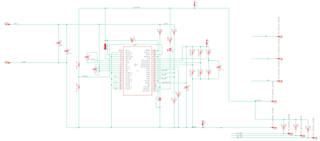
    Here is my test board circuit schematic in all its glory.   I'm hoping you can read it (I pasted a readable image, let's hope that's been preserved)


    Thank you

    Rob Stoddard

  • Robert,

    Thanks for sharing the schematic. I checked your resistor divider and it looks like you are using a 1K (Connected to 5V) and 10K resistor (connected to GND). Voltage applied to SPEED pin in DRV10970 is 4.54V which is above the minimum PWM Input logic high voltage of 2.3V. This means you are applying a 100% PWM duty cycle and that's the reason why it works in DRV10970. If you are applying 5V to VM pin in MCT8316Z, then the device might be triggering under-voltage lock fault or a different fault due to other reasons. Can you increase VM to say 8V and check if this helps? You can also check nFAULT pin to know if there are any faults triggered. This is an open drain pin so an external pull up is required.  

    Regards,

    Vishnu

  • If you see by the schematic (yea, I know having the 5v bus higher than VM is confusing, but it looks less dodgy to me that way)  the resistor divider is coming off of the 5v bus.    I have tried this with VM set to 10 volts.   The motor jumps,  the FAULT light does NOT turn on, but otherwise doesn't run.   I have the SLEW and ADV lines currently not populated with resistors (have not tuned anything)  ...  however I am curious about ILIM, since the documentation on ILIM is rather sketchy.   It suggests tying it to GND, or putting in a resistor... but I have to wonder, is that resistor to ground?  I suppose it is, but the documentation's lacking that precise point.    It could be that I'm providing a voltage to ILIM that causes the motor to shut down with the current configuration.  I honestly don't recall why I'm putting two resistors there, but I get this sneaking suspicion that I had an educated reason for it.    I initially made this design a long long time ago, so this particular detail I've forgotten, and now can't find any documentation to make sense of why I did what I did there.   So that might be my issue.

    I do have an LED on the nFAULT pin, so it should (ahem) indicate to me immediately if there's a fault.   I have seen no fault.

    Thank you
    Rob