This thread has been locked.

If you have a related question, please click the "Ask a related question" button in the top right corner. The newly created question will be automatically linked to this question.

DRV10983: How to use the reading speed feature of FG pin?

Part Number: DRV10983


Hi team,

Here's an issue from the customer may need your help:

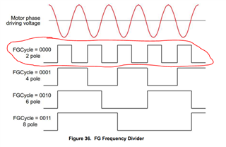
Customer currently uses the register to read speed and it could be consistent with tachometer already. But the speed calculated by capturing the pulse of FG pin is still not correct. How can they get the correct speed through this pin? 

The number of polar is 8 and the SysOpt9 in the register is set to "2 electric cycle to send 1 pulse", is "1 electric cycle" here referring to rotate for one time? 

Could you help check this case? Thanks.

Best Regards,

Cherry

  • Cherry,

    Speed register in DRV10983 outputs the motor electrical speed in Hz. Tachometer reads the mechanical speed in RPM. If both speeds match (after converting mechanical RPM to Hz), the motor should have 1 pole pair. If FGcycle in SysOpt9 is set to "2 electric cycle to send 1 pulse", then the FG will output one pulse for 2 electrical cycle as shown in below plot. For an 8 pole motor, 4 electrical cycles equal one mechanical cycle.

    Regards,

    Vishnu

  • Hi Vishnu,

    Thanks for your support.

    The problem with reading the speed was solved. But here comes a new case:

    Speed fluctuations occur at high speeds with no load. Using a monolithic to input a set of PWM signals with a fixed duty cycle to the DRV10983, the resulting speed is as follows:

    The units of vertical coordinates are RPM, and you can see that the maximum velocity fluctuation is 25 RPM.

    It was also observed that in one location, there was a speed fluctuation, as shown in the figure below, which reached 70. Why is this? Which parameters in EEPROM may cause similar behavior? 

    Thanks and regards,

    Cherry

  • Hi Cherry,

    Thanks for the additional data! Tuesday is a holiday for TI in the US, but Vishnu will get back to you once he is able to do so, hopefully by the end of the week.


    Regards,

    Anthony

  • Hi Cherry,

    Speed can fluctuate when the estimated BEMF constant is not stable. Here are the options to try.

    1. Configure control coefficient to a value lesser than 1. 

    2. Tune lead time until the estimated BEMF constant is stable. 

    Is the speed being read through FG or the speed register?

    Regards,

    Vishnu

  • Hi Vishnu,

    when the estimated BEMF constant is not stable.

    Is the estimated BEMF constant refer to the set value of MotorParam2 in the register?

    1. Configure control coefficient to a value lesser than 1. 

    If the control coefficient is adjusted to 0.5, the speed cannot be increased to the specified speed with full duty cycle (previously always set to 1).

    2. Tune lead time until the estimated BEMF constant is stable. 

    The customer is not familiar with the lead time.

    Is the speed being read through FG or the speed register?

    The speed is currently read by taking the pulses of FG. It can also be seen from the external tachometer that the motor does fluctuate at high speeds.

    The customer tried to change the value of MotorParam2 and found that setting the value higher would result in a higher maximum speed for the motor and a lower value would result in a lower maximum speed for the motor. The values of this register are adjusted to a smaller range.

    The PWM frequency is 10 KHz and the following motor parameters are used:

    24V nominal, three-phase, no-load speed 3850, current 0.12. Speed 2800 with load, current 1.5, 3.8 ohm resistance between terminals, 2.8mH inductance. And the manual also includes a back-EMF constant of 6.24 mV/rpm, but this value is much different from the estimate.

    Calculation of KT(phase-phase):

    Estimate 1:

    3850 / (60 / 8) = 513.3
    24 / 513.3 = 46.7mv/hz

    Estimate 2:

    2800 / ( 60 / 8 ) = 373.3

    (24V - 1.5A * 1.9Ω * 1.73) / 373.3 = 51.1mv/hz

    Both of these estimates are basic and the motor will work properly but will fluctuate at high speeds. 

    Also,  at 2500 rpm, the speed fluctuates considerably, and at 2700 speeds, it will fluctuate significantly smaller. The same behavior occurs when replace the motor and the chip. 

    Thanks and regards,

    Cherry

  • Is the estimated BEMF constant refer to the set value of MotorParam2 in the register?

    Estimated BEMF constant is the value read back from MotorKt1 (address: 0x15) and MotorKt2 (address: 0x16) registers.  

    The customer is not familiar with the lead time.

    Here's an app note on how to tune lead time/angle. https://www.ti.com/lit/an/slaa561/slaa561.pdf

    Regarding the BEMF constant measurement, please refer to section 8.4.1.2 in DRV10987 datasheet

    Regards,

    Vishnu