Hi team,
Here's an issue from the customer may need your help:
Assume two half-bridges are used to set the PWM complementary outputs as follows:
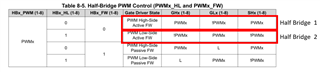
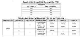
Half Bridge 1 setup: Set HB1_PWM to 00B according to Table 8-4 below, that is, Input PWM Source for half Bridge 1 is IN1, and then set HB1_HL to 0 according to Table 8-5 below. HB1_FW is 0.
Half-bridge 2 setup: Based on Table 8-4 below, set HB2_PWM to 00B as well, that is, the Input PWM Source for half-bridge 2 is also IN1, and then set HB2_HL to 1 according to Table 8-5 below. HB2_FW is 0.
Based on the settings above:
GH1 of half bridge 1 is PWM1 and GL1 is! PWM1, GH2 of half bridge 2 is! PWM2, GL2 is PWM2. Because the Input PWM Source for half-bridges 1 and 2 are both IN1, so PWM1=PWM2, ! PWM1 =! PWM2.
So can the above setting be considered a complementary output with the PWM set? The Input PWM Source is all IN1, and the timing is guaranteed.
Are the above setup and considerations are possible and correct?
Could you help check this case? Thanks.
Best Regards,
Cherry