This thread has been locked.

If you have a related question, please click the "Ask a related question" button in the top right corner. The newly created question will be automatically linked to this question.

UC2625-EP: Temperature effect on UC2625-EP

Part Number: UC2625-EP
Other Parts Discussed in Thread: UC2625,

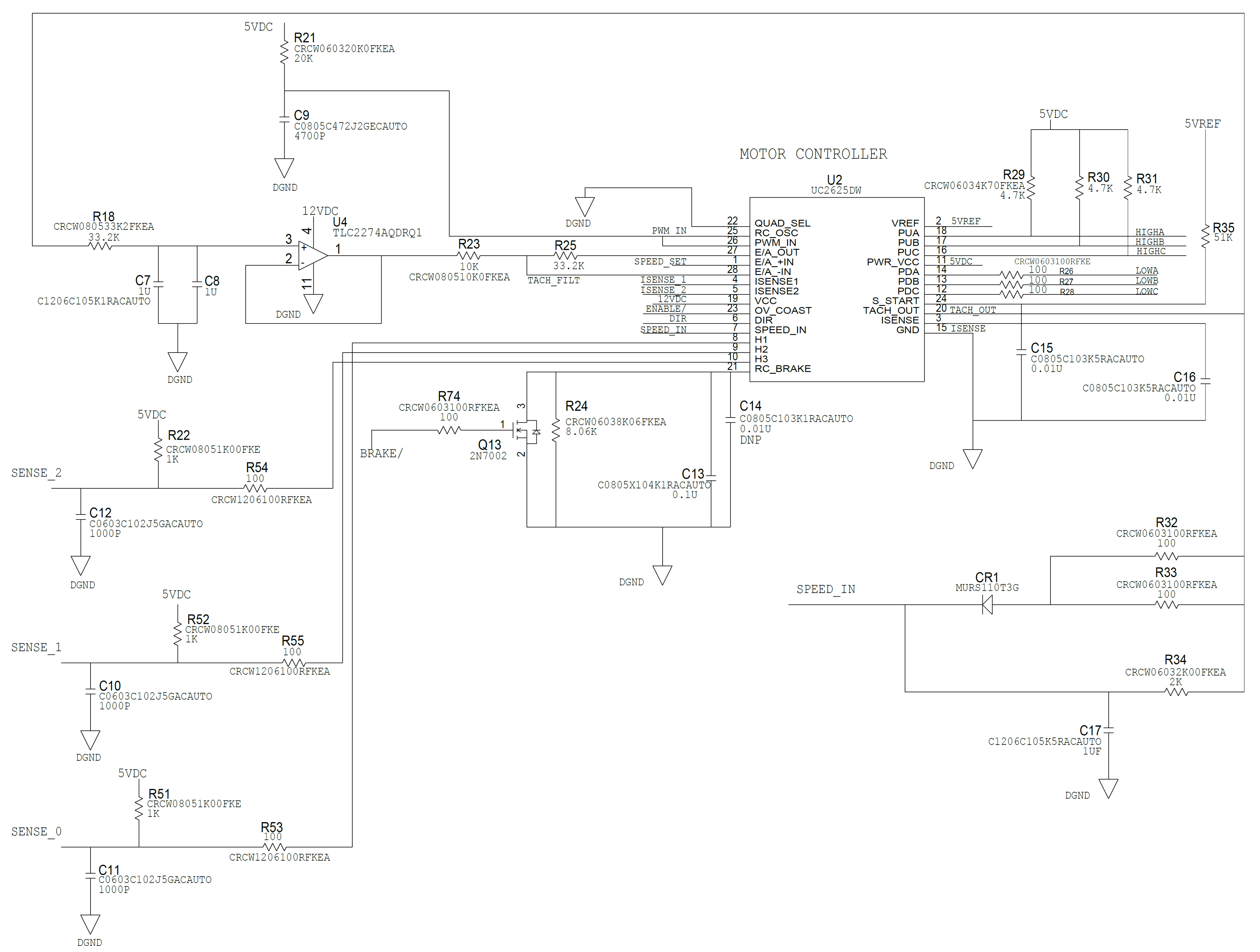
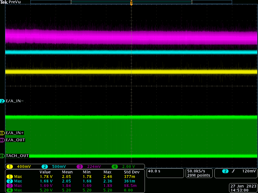
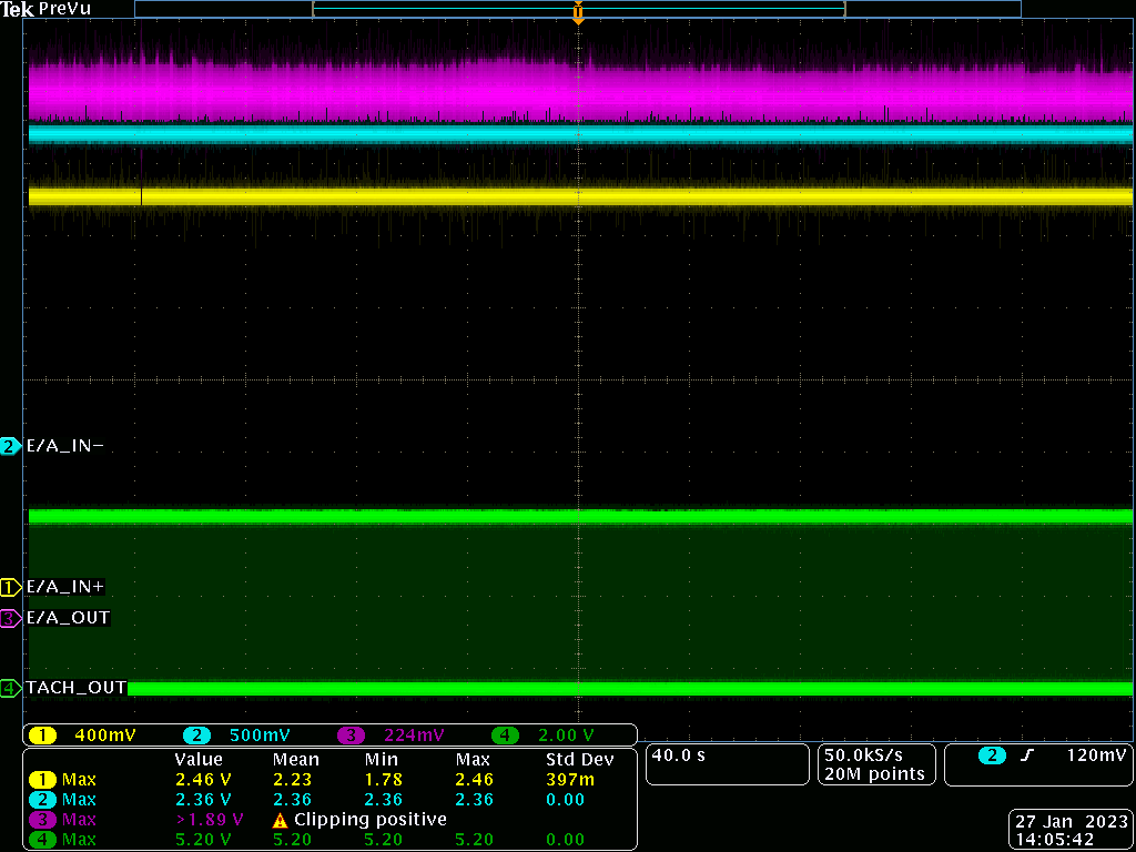
The circuit follows Voltage control mode of UC2625. The RPM of the motor keeps increasing over a period of time from the desired RPM. lets say intented RPM is 4900  but after a duration of 10 min the RPM will be 5100 and keeps increasing. we subjected the UC2625-EP to a higher temperature to 80°C. The RPM increases tremendously upto 300+ counts and reverts back during cooling phase. All other components in the PCB are thermally isolated from the UC2625-EP. Only the UC2625-EP was subjected to high temperature whereas remaining all the components at its ambient temperature 24°C. kindly post your options to resolve the issue. Thanks

  • Hi Booshan,

    Thank you for your question, I will aim to look into this more and respond by the end of the week.

    Regards,

    Anthony Lodi

  • Hi Booshan,

    To better understand your particular application would you be able to provide a schematic? That would help me analyze it better.

    Regards,

    Anthony Lodi

  • Hi Anthony,

    thanks for your response.

    It is not possible to share the entire schematic but I have attached the screenshot of UC2625 circuit for your reference. The end application is for avionics product.

    /resized-image/__size/4288x3240/__key/communityserver-discussions-components-files/38/UC2625-_2D00_-Schematic.png

    Regards,

    Booshan.S

  • Hi Booshan,

    Thanks for the screenshot! That should be sufficient for what I need, I will spend some time this week looking over it and will let you know my thoughts.

    Regards,

    Anthony 

  • Hi Booshan,

    Could you provide a snippet of the layout showing the placement of R21 and C9 with respect to the driver? These components need to be placed as close as possible to the device to avoid instability in the clock signal, so I want to check to see if that could be a contributing factor.

    Where does the SPEED_SET signal come from? does it come from a DAC from the MCU? Or is it from some other source?

    When you mention that the RPM of the motor is increasing are you determining this by looking at the hall signals? Or are you determining the RPM a different way?

    Regards,

    Anthony Lodi

  • Hi Anthony,

    Thanks for your response.

    The R21 & C9 are placed close to the driver chip. I cant able to attached the Layout snippet.

    The SPEED_SET signal is a voltage divider resistor output & the SPEED_SET signal is monitored. The SPEED_SET signal is very stable during variation in motor RPM.

    The RPM is measured by a contact type tachometer coupled to the motor shaft.

    Regards,

    Booshan.S

  • Hi Booshan,

    Thanks for the additional details! 

    Today is a TI holiday, but I will aim to provide a response by the end of the week.

    Regards,

    Anthony

  • Hi Booshan,

    Based on the information you provided, the signals that I am most interested in are E/A_OUT, E/A_-IN, E/A_+IN, and TACH_OUT. Would you be able to show these signals on an oscilloscope waveform with about 1 minute per division to see if there is some trends of increases or decreases in voltage over time? This will help to narrow down particular signals that could be contributing factors. For the voltage scale, if you could have as much voltage resolution as possible to help to detect changes in voltage that would be great. 

    Regards,

    Anthony Lodi

  • Hi Anthony,

    will share you the screen shots ASAP.

    Regards,

    Booshan.S

  • Thanks for the waveforms Booshan! 

    It appears that E/A+IN and E/A-IN is steady, despite the fact that the motor speed is increasing. It seems that there should be a slight increase on E/A_-IN since that is connected to the TACH_OUT filter which should increase in voltage as speed increases. Could it be possible that the cutoff frequency of the low pass filter of the TACH_OUT may be too low? Could you try raising the cutoff frequency (R18 and C7/C8) to see if this has any effect? Currently the cutoff frequency is set to less than 3Hz. You can raise the frequency by an order of magnitude to see if this has any effect on the speed accuracy.

    Regards,

    Anthony Lodi

  • Hi Anthony,

    Thanks for your response.

    The Exercise you were suggesting was tested already for a cutoff frequencies close to 50Hz, 500Hz & 1 KHz and it doesn't yield improvement in terms of RPM of the system. Increasing the RC cutoff frequency make the system RPM more precise but the RPM incremental Bandwidth was still the same i.e over a period of time of 10 min the RPM will increase slowly by 300+ counts.

    Our team also carried out set of experiments by adjusting Gain of the Internal error amplifier i.e. R23 & R25 and accordingly the Speed_set input was also adjusted to achieve the desired RPM. These tuning experiments also not yielded improvement to the motor RPM.

    Regards,

    Booshan.S

  • Hi Booshan,

    Thanks for the background! Does the speed ever saturate? If it is run for 1 hour is the speed still increasing? Is the rate of speed increase the same? If the speed is increasing we should see the TACH_OUT duty cycle increase which would feed back into E/A_IN- and adjust the speed. I would be interested to see if a greater amount of time (such as 1 hour or more) would lead to a greater change in speed that may be easier to see on the TACH_OUT waveform as well as on E/A-IN. 

    Unfortunately, since this is an older device we are very limited in the amount of resources and expertise that we have available to support it. One other aspect that you could check is adjusting the Rosc/Cosc values to see if that has any effect on the speed loop.

    Regards,

    Anthony Lodi

  • Hi Anthony,

    Thanks for the response.

    The RPM of the motor is not saturating but the rate of increase will be keep reducing i.e. rate of increase will be high during Power ON and reduces over a period of time. The rate of increase will be very minimal lets say after 60 min.

    The TACH_OUT positive duty cycle is between 45% to 49% and it is within the same band over 60 min Power ON.

    The Rosc & Cosc were also modified & tested for different frequencies and no improvement in the motor RPM.

    In addition the closed loop control circuit was subjected to lot of experiments and doesnot improvised the motor RPM & we cornered the problem to the temperature effect on the UC2625 by applying the high temperature upto 70°C only on the UC2625 (Monitored through thermal camera). when the heat is applied the RPM was increased upto 300+ counts & during cool down it reverts back to the balancing point (not the initial RPM during Power ON). But when we shut down the entire system & allow it to cool in ambience temperature for a hour or so.. the starting RPM point will be the same as previous test results. The similar fashion of the temperature test was conducted with all the speed loop components, biasing components & FET drive etc. in the PCB and doesnt have any impact on the Motor RPM. So as per the tests we conducted for the past months the increase in the RPM only relates to the temperature effect on the UC2625.

    The Chip part number used was UC2625MDWREP.

    Regards,

    Booshan.S

  • Hi Booshan,

    Thanks for the additional details. I will aim to provide a response by the end of the week.

    Regards,

    Anthony Lodi

  • Hi Booshan,

    For the resistor divider that sets the reference voltage for the error amplifier, is that being generated from the 5V from the UC2625? Or is it being generated from a different 5V supply? If it is being generated from a different supply, could you instead connect it to the 5V from the UC2625? I am wondering if some slight drop over time of the 5V from the UCC2625 could be causing the TACH_OUT average voltage to be lower overtime and therefore result in a higher speed since the error amplifier reference voltage would not have that same drift. 

    One other thing you could look into is this e2e post (https://e2e.ti.com/support/motor-drivers-group/motor-drivers/f/motor-drivers-forum/1034660/uc2625-uc2625) since it seems that the customer had a similar issue and was able to resolve it.

    Another thing I noticed is that the R24 value in your schematic is outside the recommended resistance range for the RC_BRAKE pin. You could try adjusting the RC values to bring the R value back in to the recommended range mentioned in the datasheet. 

    Regards,

    Anthony Lodi