This thread has been locked.

If you have a related question, please click the "Ask a related question" button in the top right corner. The newly created question will be automatically linked to this question.

DRV2511-Q1: Odd TINA simulation results for AC analysis

Part Number: DRV2511-Q1

I'm trying to build a motor driver using the DRV2511.  It needs to be DC coupled and I'd prefer to work out the details in TINA before creating a protoboard.  Using the TI reference design "slom423.tsc" I get the following results which don't agree with each other.  For transient response the system shows a voltage gain of 10, or 20db, exactly as expected for the default FS0-2 gain settings.  Input is 1V and output is 10V.

However, looking at the ac response gives a magnitude of -172db at 1kHz (equal to voltage gain of 2.5e-9) which makes no sense to me.  I would expect a magnitude of 20db.

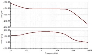
Any idea what causes this error and how to correct it?  This is needed to develop the proper control loop.

  • Hi,

    Our TI experts are out of office today for US holiday so please be patient as responses may be delayed.

    Thank you for your patience.

    Regards,

  • It's been two weeks.  Can someone have a look at this and confirm I don't just have some incorrect simulation setting?  I cannot seem to get a reasonable output.  

  • Hi Brian, 

    Sorry for the delay, I have been catching up since the holidays and some business travel last week. 

    I did take a look at this and see the same result. that being a difference between the transient analysis and the AC transfer characteristics. 

    It seems to be due too how the AC analysis is performed. AC analysis is performed on a small signal AC that may be significantly smaller than the actual typical signal level. this is a good article that is discussing the same discrepancy that you have created this post about. https://www.eeworldonline.com/spice-how-to-choose-an-analysis/ 

    "The difference between the two simulations is the difference between small signal analysis and large signal analysis. The small signal (AC) analysis doesn’t show how the circuit will be used realistically ( i.e., with a large signal). You could duplicate the AC analysis results with the transient analysis but not the other way round."

    you should base your design simulation on the Transient analysis results, In addition I am also here to help as needed throughout your design.

    Regards,

    Arthur

  • Hi Arthur,

    Thanks for looking into this.  

    Unfortunately, it's not really an answer I can work with.  The transient analysis takes minutes for each iteration.  To 'simulate' a large AC response would take days and not be a realistic method for developing a control loop around this device.

    I'm not sure how small the default AC signal is done, I thought it was 1V?  But regardless the device should operate in the low mV or it won't be usable in our application anyway.

  • HI Brian, 

    Understood, Can you share some details about what the final application will be? I will likely need to ask on E2E to fellow TIers to find a solution, it may help if I can know the final goal. 

    Regards,
    Arthur