This thread has been locked.

If you have a related question, please click the "Ask a related question" button in the top right corner. The newly created question will be automatically linked to this question.

DRV8353: DRV8353 Synchronous 1xPWM Mode Switching Scheme Issue

Part Number: DRV8353

Hi,

We are using DRV8353 (DRV8353RHRGZR to be exact) to drive the gates of the MOSFETs in a three-phase inverter used to drive a BLDC motor. We set the driver in "Synchronous 1xPWM Mode" which is the recommended mode of operation for the control of three-phase BLDC motors. However, we believe that the commutation table (Table-3 in the datasheet) for this operation mode is incorrect. We believe that the generated magnetic field vector according to the rotor position (hall sensor inputs) is not placed at the correct angle with respect to the rotor position. We expect that the angle between the rotor magnetic field vector and the created stator magnetic field vector should change between 120 degrees to 60 degrees (six step operation). In this way, we maximize the torque output per ampere (MTPA) by keeping the angle between the two magnetic field vectors at and around 90 degrees (torque is proportional with the sinus of the angle between these two vectors). However, for the commutation table which is provided in your datasheet (Table-3), for one direction (INHC=0) this angle varies between 60 degrees to 0 degrees and for the other direction (INHC=1) it varies between 120 degrees to 60 degrees. This, in turn, creates a no-load speed difference for two direction of rotations. In one direction, the motor speeds beyond its specified no-load speed for the given bus voltage, and in the other direction it is not able to reach its no-load speed. This, we believe, is because of the above mentioned angle difference between the two magnetic field vectors. In one direction, it weakens the magnetic field of the permanent magnets on the rotor, which in turn increases the no-load speed (field-weakening action). In the other direction, it, in contrast, strengthen the magnetic field of the rotor, which reduces the no-load speed of the motor since the generated back emf voltage is higher for the same speed. We observed that case in our setup. When we use the gate driver in the "Synchronous 1xPWM Mode", with the closed loop current controller implementation, the motor speeds up beyond its no-load speed specified in its datasheet for the given voltage, and for the other direction the motor is unable to reach its no-load speed. Furthermore, the motor is buzzing and vibrating anormally for the both direction of rotations.

After making those observations and inferences, we also tried the other swithing scheme that we believe the correct way of commutation. I shared the commutation table that we implemented below.


According to this commutation table, you let the current flow through the motor phases such that the angle between the rotor magnetic field and stator magnetic field changes between 120 degrees to 60 degrees for each hall sensors combination and for both direction of operations. When we applied the voltage to the motor according to this commutation table, the motor reached the specified no-load speed in the datasheet for both direction of rotations. Furthermore, we didn't observe the vigorous buzzing and vibrating action from the motor anymore. It started operating smoothly and more silently. Also, when we search through the internet, the most common commutation table is the one I shared in the above image. Therefore, we believe the commutation table (Table-3) for the "Synchronous 1xPWM Mode" shared in your datasheet might be incorrect or improper for the BLDC applications.

  • Hi Fahri,

    Thank you for posting to the Motor Drivers forum!

    Unfortunately, I did no get the chance to look at this today, but will get back to you with a response shortly.

    Best,

    ~Alicia

  • Hi Alicia,

    Thank you for paying attention. Did you have a chance to look at it?

  • Hi Fahri,

    Thank you for your patience.

    Would you be able to share a waveform of the INHx and INLx as well as the GHx and GLx to further investigate if the truth table listed in the datasheet? Also, would you mind sharing a schematic of your system?

    Best,

    ~Alicia

  • Hi Alicia,

    I think, there is a theoretical problem with the switching scheme given in Table 3 in the datasheet. This, I believe, is independent of any circuit design. For instance, let's say the hall data is [H_A H_B H_C] = [1 0 0]. In this case we expect the rotor to be within the +/- 30 degrees of the magnetic axis of Phase A. Therefore, in order to create the maximum average torque, the MOSFETs should be switched such that current flows through Phase B and Phase C (current direction changes according to the direction of rotation). In this way, the magnetic field vector created by the currents flowing through the stator windings is set to 120 degrees ahead of the rotor magnetic field vector (which is in this moment aligned with the magnetic axis of Phase A). Thereby, for each sector, the angle between the two magnetic field vectors changes between 120 to 60 degrees. However, for the switching scheme given in the Table 3 of the datasheet, for the same hall sensor input, the current is let to flow through Phase A and Phase C, which creates a 180 to 120 degrees change in one direction and a 60 to 0 degrees change in the other direction between the two magnetic field vectors.

  • Hi Fahri,

    The following E2E threads may be useful as these users experienced a similar issue to what you are seeing:

    These users found that their hall sensors were misaligned and when corrected, they were able to resolve the issue.

    The following FAQ is a great resource in checking to make sure that your hall sensors are aligned with your rotor:

    Best,

    ~Alicia

  • Hi Fahri,

    After making those observations and inferences, we also tried the other swithing scheme that we believe the correct way of commutation. I shared the commutation table that we implemented below.

    1. I don't know where did you get the 6-step commutation logic shown in Table1 below, but this is not the industry standard that I know. This table could be specific to one type of motor from a supplier. The only way to confirm your table 1 is good for your motor, is to capture the BEMF of the 3 phases and the Hall signals during the rotor rotating for 360* electrical cycle. 

    2. The datasheet Table 3 is the well known industry standard provided by every BLDC motor that I known, so it cannot be wrong. As I said above, perhaps your motor is a special one. Can you provide the datasheet for your motor including the 6-step logic table?

    Brian

  • Hi Fahri,

    However, we believe that the commutation table (Table-3 in the datasheet) for this operation mode is incorrect. We believe that the generated magnetic field vector according to the rotor position (hall sensor inputs) is not placed at the correct angle with respect to the rotor position.

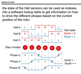
    Without seeing the waveform of the 3 phase voltages and the Hall sensor signals of a motor, one can't tell if the commutation table logic is right or wrong. Below is the waveform of a motor from Ti article. From this, at each of the step, we can easily tell the voltage to be applied to each motor phase based on the logic signals of the Hall sensors.

    Brian

  • Hi Brian,

    Thank you for your feedback. I've checked the hall sensor alignments with the stator phases. For that, I applied a different method. First of all, I connected the stator phases to the voltage source such that Phase A is connected to the (+) of the supply voltage and Phase B & C are connected to the (-) of the supply voltage. In this case, I expect rotor to be aligned with the magnetic axis of Phase A, in which case the Hall sensor data should be like [H_A, H_B, H_C] = [1, 0, 0]. The same is also applied for the other two phases of the motor. When I tested the motor like that, I confirmed that the hall sensor data are correct for each alignment. Then, to make sure that the alignment is exact, in other words, there is no angle shift between the hall sensor placement and the stator phase magnetic axes one way or the other, I applied the below voltages to the stator phases and after the rotor alignment is completed, I rotated the rotor a little bit in both CW and CCW directions to see how the hall sensor data change. With the below voltages in each row applied to the stator phases, the rotor aligns to the each one of the 6 sector borders. Therefore, if the rotor is a little rotated CW or CCW, the hall sensor data should change as specified below. I tested it and confirmed that the hall sensor data are in line with the data given below. Hence, I confirmed that the hall sensors are correctly aligned with the stator phases. Therefore, I still believe, the switching scheme given in the Table-3 of the datasheet, is not correct. Because the angle between the stator magnetic axis and the rotor magnetic axis changes between 180 degrees to 120 degrees for one direction and it changes between 60 degrees to 0 degrees in the other direction. Although, since the torque is proportional with the sine of this angle, the average torque of them are equal, their average cosine, which is the field component, are not equal. It is like applying a positive Id current in one direction and a negative Id current in the other direction, which explains the no-load speed difference in two directions because you are strengthening the field in one direction and weakening in the other direction I believe.

    O: Not connected

    + : Connected to the (+) of the supply

    - : Connected to the (-) of the supply

    Phase A      Phase B     Phase C         Sector Change             Hall Sensor Data Change [H_A, H_B, H_C]

        +                  -                 O                        1-2                                           [1,0,0] - [1,0,1]

        O                  -                +                         2-3                                           [1,0,1] - [1,0,0]

        -                  O                +                         3-4                                           [1,0,0] - [0,1,1]

        -                  +                O                         4-5                                           [0,1,1] - [0,1,0]

        O                +                  -                         5-6                                           [0,1,0] - [1,1,0]

        +                 O                 -                         6-1                                           [1,1,0] - [1,0,0]

  • Hi Fahri,

    Are you able to provide a datasheet of the motor that you are using? As Brian mentioned, it could be that the motor that you are using is a specialized one that may require a different commutation than the standard commutation specified in Table 3 of the datasheet.

    Best,

    ~Alicia

  • I've checked the hall sensor alignments with the stator phases. For that, I applied a different method. First of all, I connected the stator phases to the voltage source such that Phase A is connected to the (+) of the supply voltage and Phase B & C are connected to the (-) of the supply voltage. In this case, I expect rotor to be aligned with the magnetic axis of Phase A, in which case the Hall sensor data should be like [H_A, H_B, H_C] = [1, 0, 0].

    This is not the correct way to verify the commutation table. Note: at each step, current only flows through one phase (from A to B for example), not two phases as you did by connecting both B and C to (-) of PS. If we post the Hall signal logic states at with current flows through the phases as below, we can verify it.

    AB

    AC

    BC

    BA

    CA

    CB

    Brian

  • Hi Brian,

    Thank you for your quick return. You're right. But I did that test only to align the rotor with the magnetic axis of the each phase and see if the hall sensor data are correct (whether only the hall sensor of the aligned phase is outputting 1, and the other two are outputting 0). After confirming that, I did the test I shared in the table above, which is same as what you stated above (letting current to flow through only two phases at a time). And I confirmed the hall sensor data changes are in line with what is expected.

  • Hi Alicia,

    It is actually one of our SM PMSM motors that we use in our servo control applications. We drive it with Field Oriented Control technique without any problem. We converted it to a BLDC motor by changing only the sensor of the motor from resolver to hall sensors & encoder. Its back-emf is sinusoidal again. We might think it as instead of controlling this motor with FOC, we are controlling it with six-step control technique with a different position sensor.

  • Hi Fahri,

    Thanks for the information! Today is a TI holiday, we will aim to provide a response by the end of the week.

    Regards,

    Anthony 

  • Hi Anthony,

    Thank you for informing. No problem. Have a nice holiday Slight smile

  • Hi Fahri,

    As a sanity check, are your hall sensor's digital outputs from the motor connected to the DRV8353 as follows: INLA = HALL_A, INHB = HALL_B, INLB = HALL_C?

    The following TIPL videos are great resources on the 1xPWM commutation method used:

    As Brian mentioned, 

    Without seeing the waveform of the 3 phase voltages and the Hall sensor signals of a motor, one can't tell if the commutation table logic is right or wrong.

    Best,

    ~Alicia

  • We converted it to a BLDC motor by changing only the sensor of the motor from resolver to hall sensors & encoder. Its back-emf is sinusoidal again. We might think it as instead of controlling this motor with FOC, we are controlling it with six-step control technique with a different position sensor.

    OK, so you added the Hall sensors to this motor and ended up with the Hall signals 60* electrical ahead of the Ti's standard table. There is nothing wrong with your table or the Ti's table; the difference is where the Hall sensors were located relative to the stator phase coils. Obviously if your Hall sensors are retarded 60* electrically then you can use the Ti's driver table.

    BTW, Maxon motors are with the Hall sensors 60* elec retarded from Ti's table.

    Brian

  • Hi Brian,

    Do you mean that your commutation table is based on hall sensors placed 60 electrical degrees shifted from the magnetic axes of the stator phases A, B and C? If it is so, then you're right. The commutation table in Table-3 works fine. But I couldn't find any information in the datasheet about the assumed hall sensor placement with respect to the stator phases. Is there any information about it that I missed? Because, as you said, the commutation table strictly depends on how your hall sensors are placed in the circle of the stator.

    My assumption was Hall A is exactly aligned with the magnetic axis of phase A, Hall B is exactly aligned with the magnetic axis of phase B and Hall C is exactly aligned with the magnetic axis of phase C.

  • My assumption was Hall A is exactly aligned with the magnetic axis of phase A, Hall B is exactly aligned with the magnetic axis of phase B and Hall C is exactly aligned with the magnetic axis of phase C.

    No. If this was the case, then Maxon motors and everyone else motor in this world should have the same kind of table, but they are not. 

    Ideally, the Hall signals should be aligned such that Hall A high should be center with VAB phase voltage high BEMF, and Hall A low should be center to phase AB low BEMF. This means Hall signal high is 180 electrical deg, and low is 180* . The same are for B and Vbc;  and C hall signals with Vca. The Ti 6-step table is based on this alignment.

    This means with current flows through phase A to B, the rotor magnet will be locked at a position that causes the Hall A to change from high to low, right in between the two states.

    Your setup is not followed this convention. 

    Brian

  • Thank you Brian. This resolves my issue then. Appreciate your time and help. But I think it would be helpful if you state the assumed Hall Sensor placement orientation in your datasheet because when I search through internet, it seems everyone is adapting some how a different orientation on that, which makes it very confusing. In fact, it is the simplest kind of drive technique, much simpler than FOC, but this confusion about the hall sensors makes it harder to comprehend.