This thread has been locked.

If you have a related question, please click the "Ask a related question" button in the top right corner. The newly created question will be automatically linked to this question.

DRV8412: Unexpected OC Latching Shutdown

Part Number: DRV8412

Hello, we are currently troubleshooting our DRV8412 design because we are experiencing latching shutdowns while driving a stepper motor at currents of greater than 3A.

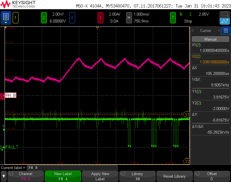
I believe we have eliminated undervoltage protection as the reason for shutdown by probing GVDD during FAULT conditions. There is no significant droop on our 12V GVDD supply (approaching 8.5V UVP threshold) at the time that FAULT is asserted, and we have further reduced this risk by including additional local decoupling at the DRV8412 GVDD pins. Also, we have found that the OTW pin remains HIGH during FAULT conditions.

Therefore, I believe we are experiencing an overcurrent shutdown (Level 2).

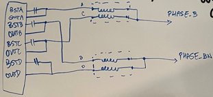
Below is our design using individual DRV8412 parts to drive each phase of a stepper motor. We are using paralleled outputs to increase the current drive capability of the design.

Please note that since we have started troubleshooting, we have modified the above schematic design with the following:

  • C419-C422, C441-C444 with 2.2uF capacitors
  • R351 & R391 with 27kΩ resistors (OC threshold = 9.7A)

Even though the currents passing through the windings (~3A RMS) are not close to the OC threshold (9.7A), we thought it possible that some current was shooting through the low-resistance paths directly between OUT_A & OUT_C, and OUT_B & OUT_D on each DRV8412.

To test a fix for this, we altered the output inductor configuration to match Figure 15 from the DRV8412 datasheet, in line with the recommendation in Section 9.4.5. This is summarized in the diagram below.

Doing so led to slightly less frequent FAULT conditions from OC latching shutdown when running at over 3A RMS, but these failures would still occur. We also tried placing the DRV8412 into Mode 3 for Parallel Full-Bridge outputs (which required reworks on both input PWM and output drive configurations), but did not see a noticeable difference between the functionality of the design or frequency of FAULT conditions.

Also, it may be important to note that the output filter we are using is the common mode filter SBP-5001T.

Can you please review our design and implemented reworks to suggest possible tests and fixes for our operation?


Thank you.

  • Hello,

    It sounds like you have done a significant amount of debug work and if you are seeing latching in CBC mode, then it should be level 2.  

    Have you tried removing the CM filer on the outputs as a quick test?  I have seen issues with these type of filter networks before.  

    Regards,

    Ryan

  • Hello Ryan,

    Yes, I believe that it is an OC Level 2 latching shutdown.

    I have tried removing the CM filter and shorting across the pads, but this led to very fast shutdowns (~10ms).

    Perhaps you can suggest some different output filter configurations to test?

    Thank you,

    Danny

  • Danny,

    Just so I am clear, removing the CM filter made the shutdowns faster?  Are you seeing this on more than one stepper motor?  I have seen stepper motors fail and cause similar behavior.  

    Is there anything else hanging off the outputs that is not shown in the schematic?  Have you tried resistive loads?

    Regards,

    Ryan

  • Hi Ryan, we have determined that tests with the below 1A stepper motor are not viable. If possible, please prioritize the question regarding potential CBC limiting.

    I only tested without the CM filter on one stepper motor and yes, it caused a faster shutdown. However, your point about failing stepper motors made me take a second look at the motor I was currently using and made me realize that I had inadvertently switched the stepper motor following a rework to one with a lower 1A/phase rating. After seeing the shutdown, I probed the winding resistances of this 1A motor and saw nothing out of the ordinary. I am not familiar with the mechanisms of stepper motor failure, but is it possible that this 1A motor temporarily failed due to a current overload and caused the FAULT to assert (level 2 OC shutdown)? If it failed and created a temporary short, I would expect to see a spike at the time of failure on my current probe (I did not).

    Also, there is nothing hanging off the outputs, as they go directly to an off-sheet connector. I have not tried resistive loads.

    Thank you,
    Danny

  • Hi Ryan, 

    In addition to the above question regarding stepper motor failure modes, I have another question about the FAULT behavior while operating at about 3.7A. 

    I have switched back to the higher current-rated stepper motor and with my current configuration, it successfully protects against shutdown at HOLD (DC) currents of 3.2A. To test the limits of its overcurrent protection, I increased the current to about 3.7A DC and saw the following behavior. Note that the magenta trace is Phase B winding current and the green trace is the FAULT signal.

    After reaching the 3.7A DC level seen above, both waveforms continue for 700ms until the FAULT fully asserts and PH B current drops to zero. To me, this appears to be CBC current protection. Would you agree?

    If it is indeed CBC protection, do you know why it is occurring at a current of 3.7A DC when the OC_ADJ resistor is set to 27kΩ, resulting in a 9.7A OC protection threshold?

    It may also be important to note that the pictured Phase B current corresponds to a DRV8412 (U64 in schematic) currently in Mode 1, whereas the other Phase A DRV8412 (U66) is in Mode 3. U66 continues to output phase drive signals after the FAULT on U64 asserts. Based on my understanding of the datasheet, however, the DRV8412 mode should not affect the OC_ADJ threshold, as the CBC current limit should be independent of each half-bridge.

    Thank you,

    Danny

  • Danny,

    Can you also plot at least one input and corresponding output on the scope capture?  If input does not match output, you are in CBC as CBC will truncate the input pulse until the next rising edge on that input.

    Also, there is a note in the datasheet for mode 3.  One of the advantages of mode 3 is synchronized internal switching even during CBC.  Without using Mode 3 in your configuration, you really can get some unpredictable behavior.

    Regards,

    Ryan

  • Hi Ryan, 

    I had already reworked the Phase A driver (U66) to set it to Mode 3 prior to your reply. With this configuration of both drivers in Mode 3, I am not seeing any FAULT pulses that may indicate CBC current limiting. 

    Instead, I am seeing that 1 of the 2 drivers will FAULT instantly upon reaching the 3.7A DC level without any evidence of CBC limiting (looks like Level 2 OC shutdown). However, the driver which FAULTs is directly dependent on the desired direction of the rotation drive command. If I send a "Move POS" command, the Phase A driver (U66) will fail instantly upon reaching its max current. If I send a "Move NEG" command, the Phase B driver (U64) will fail instantly upon reaching its max current.

    Move POS - Phase A Driver faults
    A+ negative current; A- positive current; B+ positive current; B- negative current

    Move NEG - Phase B Driver faults

    A+ positive current; A- negative current; B+ positive current; B- negative current

    Have you ever experienced similar behavior using this or a similar part, and can you provide any suggestions?


    Thank you,
    Danny Morejon

  • Danny,

    Can you verify that /OTW pin is high indicating no thermal trip?

    Can you provide scope captures of the current and corresponding fault?  Is it a latched fault?

    Is the GVDD voltage solid?  

    Regards,

    Ryan

  • Hi Ryan, 

    We are currently using a different configuration in which we have disconnected the OUT_C and OUT_D traces on each motor such that the OUT_A and OUT_B signals are sourcing the full current. In this configuration, we are able to drive the motor at a consistent 3.7A DC without shutdown (likely due to lack of connection between DRV outputs). 

    We are going to continue testing this configuration for now, but I will restore the previous configuration and send over these captures as soon as I can. In the meantime, I can say that the OTW pin was remaining high through FAULT and I was experiencing a latched FAULT.

    Thank you,
    Danny Morejon

  • Hi Daniel,

    Ryan is out of the office this week. He will get back to you with a response once he gets back. Thank you in advance for your patience.

    Regards,

    Pablo Armet

  • Danny,

    If you are not seeing any faults with OUT_A and OUT_B sourcing all of the current, then we can rule our temperature dependencies.  Sounds like it is a "false" OCP that is occurring with the parallel connection.  Using Mode 3 should address this.

    Regards,

    Ryan