Other Parts Discussed in Thread: DRV8303
Hi all
Would you mind if we ask DRV8308?
There are descriptions as follows on the document salvu41f;
"To optimize flutter performance, vary ADVANCE, SPDGAIN, and many combinations of the FILK1, FILK2, COMK1, and COMK2 filters.
These filter settings can be changed in real-time while the motor is spinning,
but the new total gain is only updated when the motor restarts (technically when LOCKn transitions to low if AUTOGAIN is enabled).
In many cases, setting Pole1 to a much higher frequency than the others and setting Zero2 to Pole2 to a frequency band between Zero1 and Pole1 works well.
Try many combinations to find the correct settings.
Feel free to post any questions to the TI E2E Forum online."
<Question1>
"but the new total gain is only updated when the motor restarts (technically when LOCKn transitions to low if AUTOGAIN is enabled)."
Our customer changes the motor voltage from 10V to 24V gradually.
In this case, the motor could not rotate correctly.
However, in case of DC24V insert with startup, the motor could rotate normally.
So, is it relation to this "the new total gain is only updated when the motor restarts"?
<Question2>
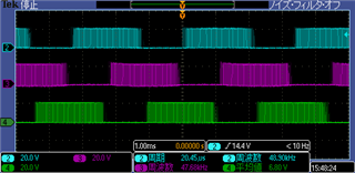
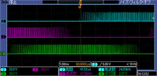
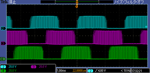
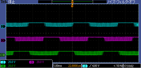
And then, the customer's motor rotation is unevenness.
So, they should vary ADVANCE, SPDGAIN, and many combinations of the FILK1, FILK2, COMK1, and COMK2 filters?
Or, they should vary followings, as the documentation salvu41f says?
"3. Turn on the clock, and start the motor with ENABLE. If the motor spins very roughly,
• Try reducing or increasing f CLKIN to find a practical case as a baseline reference.
• Try changing the filters (FILK1, FILK2, COMK1, or COMK2) with different combinations in
increments of 150. Spend some time to find good values.
• Try increasing SPDGAIN and LOOPGAIN."
Kind regards,
Hirotaka Matsumoto