This thread has been locked.

If you have a related question, please click the "Ask a related question" button in the top right corner. The newly created question will be automatically linked to this question.

DRV8245-Q1: the cooling solution of locked rotor current.

Part Number: DRV8245-Q1
Other Parts Discussed in Thread: DRV8145-Q1

Hi team,

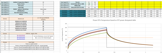
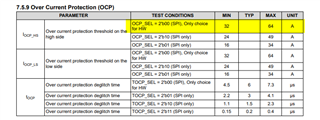
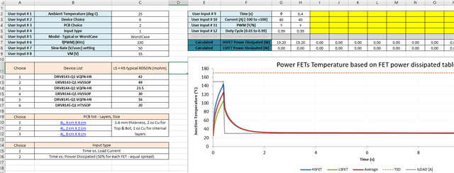
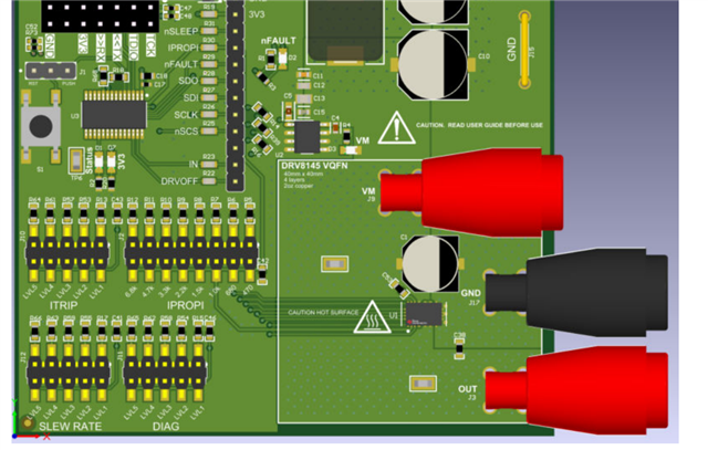
What is the locked rotor current of DRV8245-Q1? If  locked rotor current is 30A, lasting 500ms, what is the cooling solution and how large is the area of the cooling plate? Is there anything else about cooling design should be aware of?

  • Hello,

    We have a thermal calculator available on the product page.  

    https://www.ti.com/product/DRV8245-Q1

    Scroll down and you will find it under "design tools and simulation".  This can be used to model your system.

    You may need to consider a DRV8145-Q1 to thermally handle this current.

    Regards,

    Ryan

  • Hi Ryan!

    Thanks for your help. I am not sure that if locked rotor current is 30A, lasting 500ms, what input type should be selected?

    And I set the parameter as shown above, it seems that the temperature is too high for device. The current is 30A < 32A, and the temperature is above 300, What selection do I need to change?

    I also set the similar parameter when using DRV8145-Q1. And it seems that the temperature is acceptable.

    But does the DRV8145-Q1 have over spec about 30A locked rotor current?

  • Hale,

    Input type you chose is correct.  Everything looks normal to me.  

    I don't understand your last question.  Can you please explain what you are looking for?

    Regards,

    Ryan

  • Hi Ryan!

    So the datasheet showed that the DRV8245-Q1 can standby 32A, but I set 30A and the device is over temperature. Is it normal?

    And is DRV8145-Q1 the most suitable driver device for H bridge, Iout=30A lasting 0.5s in our products?

  • Also my question is about locked rotor current and I'm not sure whether it is ok that using output current replaces locked rotor current.

  • Hale,

    The 32A specification is PEAK current based on our OCP protection.  It is not meant to be a continuous current specification.  You have to use the thermal calculator, as you did, to determine temperature rise over time.  

    Based on your calculations, I would say the DRV8145-Q1 is the most suitable driver for the application.

    Locked rotor current is essentially V = IR.  The locked current will be the voltage applied to the motor divided by the resistance of the motor.  It is pretty straight forward.

    Regards,

    Ryan

  • Hi Ryan! Thanks for your support! Your statement is clearly. Just one question: if I calculate the the thermal design about locked rotor current, I need to calculate the current by VM/load(motor resistor). Is that right?

  • Correct!!!

  • Hi Ryan,

    According to the customer request, they want the PCB size is smaller than 5*5 cm with 2 layers because of 4 layers high cost. Can we use the DRV8145-Q1 to design pcb which meet their requirements? Or do you have any other suggestion ?

  • Hale,

    Please use the 1/2 bridge calculator available in the product folder.  Choose choice 2 for the calculation which is a 2x2 4L board.  This will be the closet option to what they want to do.

    Regards,

    Ryan

  • Hi Ryan,

    Thanks for your reply. So if we use DRV8145-Q1 to design 5*5 2L board, can heat dissipation be solved? And I use the thermal calculator to calculate 40A for 400ms, the temperature is above 130℃ as shown below. If we use 5*5 2L board, will the device temperature drop? The customer hopes to find a device can stand 40A for 400ms. And it seems that DRV8145-Q1 is the best choice, and can we solve the heat dissipation issue by PCB design?

  • Hale,

    If they need an integrated device, the DRV8145-Q1 is the only option.  If 130C is too high, they would need to consider a gate driver like the DRV8705 or DRV8706.  

    Did something change as I thought the original requirement was for 30A, 500ms?

    Regards,

    Ryan

  • The requirement for 30A, 500ms is proposed for locked rotor current. They need to leave some margin. So they hope that the requirement for Driving current 40A , 400ms is acceptable for DRV8145-Q1. And we need to confirm with you if DRV8145-Q1 can stand 40A , 400ms with about 5*5 2L pcb design?

  • Hale,

    The customer will honestly need to build a prototype and check it.  From simulation with smaller 4-layer board, it looks promising.  BTW, it would be impossible to get 40A out of a motor that has a locked rotor spec of 30A.  Adding margin doesn't make much sense.

    Regards,

    Ryan 

  • Hi Ryan,

    Need to be clear. If the customer use DRV8145 to replace DRV8245, they have to use 2 devices and the heat dissipation need double size PCB. But we provide 2*2 4L is used for 1 DRV8145. And as we said, the customer has to use 5*5 2L board. Also we have MCU、LIN、LDO and Hall on the 5*5 2L board. It seem that it's challenge for our PCB design. Could we have an overall arrangement or 2 pcs DRV8145 arrangement about this case?

    Also how does 2 pcs DRV8145 achieve forward, reverse, and speed regulation? How to realize it?

  • Hale.

    Yes, you will need 2x DRV8145 for directional control of the motor (forward/reverse).

    Please study the truth table in the datasheet to understand the control to realize forward, reverse, and recirculation.  If you spend time, you will understand it clearly.  

    For example, for forward...enable high-side MOSFET on one DRV8145-Q1 and enable low-side on the other DRV8145-Q1.  For reverse, flip this state.  PWM is possible for speed control.

    What oz copper will the customer use?  I recommend 2oz copper on top and bottom and entire bottom side should be just copper...no components. 

    By the way, the IC has current regulation capability to limit the current under locked rotor condition.  This will help with thermal.  Have they considered this?

    Regards,

    Ryan

  • Ok, Thanks for your patient reply. I will check the truth table in the datasheet.

    As for oz copper, I will recommend 2 oz copper on the top and bottom to the customer. And as you said, the entire bottom side should be just copper... no components. So we need to arrange all device on the top including MCU、LIN、LDO、Hall device and 2 motor driver. It's a challenge for them to arrange device on one side. And will MCU be influenced by temperature or heat dissipation?

    They didn't think about the function that the IC has current regulation capability to limit the current under locked rotor condition. How does current regulation capability limit the current under locked rotor condition? It will be useful for us to win. Can you explain it?

  • Hale,

    There is a complete section in the datasheet on current regulation.  It is a current chopping technique.  When current limit is hit, the device will turn off for a fixed period of time and then re-enable the outputs.  This continues until current drop below the trip point.  

    Are they using a TI MCU?  If not, they need to check temperature effect with their supplier.

    Regards,

    Ryan

  • We want to talk about TI M0 as their MCU. And because we see that on the EVM, the DRV8245 4*4 4L board is isolation and the other device is displayed on the other position on the board, as shown below. So we are not sure that if other device can be placed on the 4*4 2L board. And the temperature maybe influence the performance of the device not only MCU, but also LDO, LIN, Hall and as so on. We are proposing the TI solution so we need to think about all of the design challenge. Do we have experience about this PCB design?

  • Hale,

    Yes, my team designed it, so we definitely have experience. :) 

    We did that design NOT to isolate heat from MCU and other components, but to bound the board area used for thermal heatsinking to that square.  We used this information to validate our thermal calculator.  In a real design, you would not do this.  There is no need.  

    Regards,

    Ryan