Other Parts Discussed in Thread: MCF8315A,
Hi team,
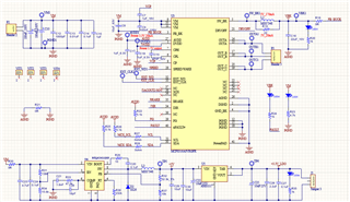
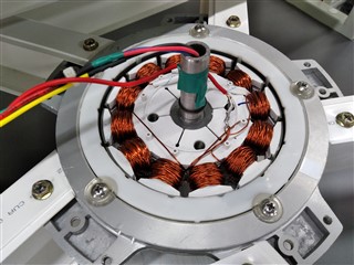
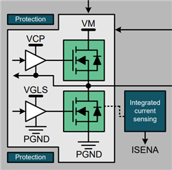
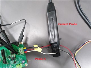
We have a fan design project. Based on MCF8316EVM board design of TI, we designed own MCF8316AEVM board with a GUI connection for the first design version.
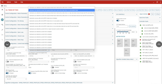
We tested our motor that had parameters below. We don't run MPET, instead, we imported directly motor parameters that is available before:
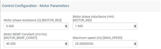
The maximum motor's speed is 240rpm. PWM is 10kHz in continuous mode and speed control via I2C
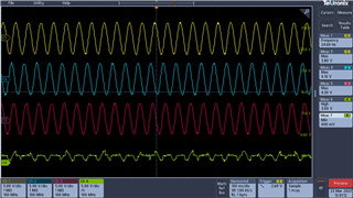
After learning and testing, our motor runs smoothly from open loop to closed loop when low-speed reference (less than 85% of maximum speed reference).
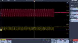
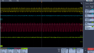
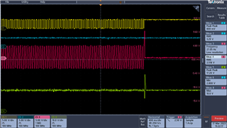
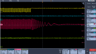
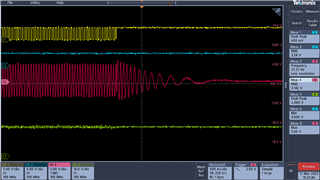
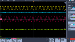
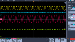
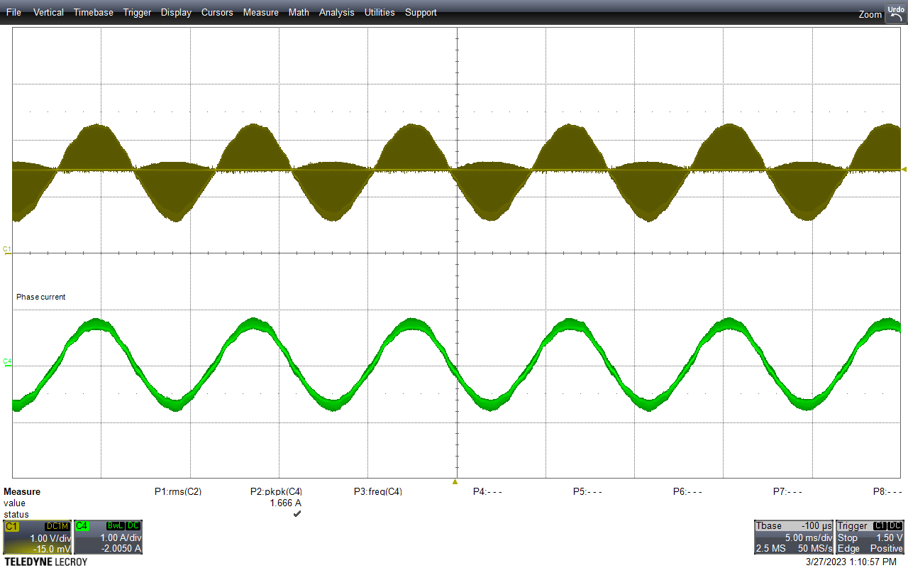
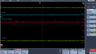
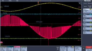
Here is our results about ground-to-phase current (red), ground-to-phase voltage (green), and FG (yellow)
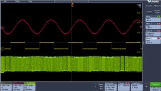
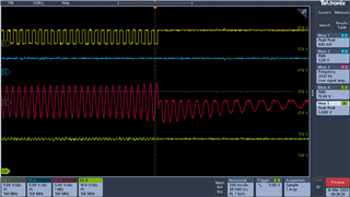
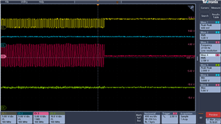
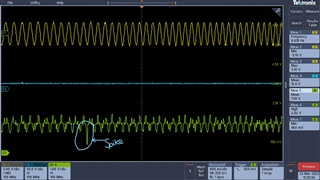
Our recent problem is that when the speed reference is set to more than 85% of maximum speed (high-speed reference), our motor still runs well in closed loop quickly, but it automatically stops without any fault alarm, and then its state returns to IDLE. Sometimes, when we set to more than 85% of the maximum speed, the power suddenly shut down because of an overcurrent error.
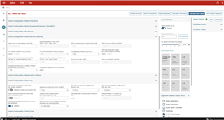
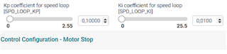
In order to fix our fault, we increased the power voltage Vm and the Lock current limit (in Control Fault Settings) up to the max value (8A) but the motor is still stopped without any fault alarm.
We hope your team to explain our problem and give us the solutions.
Regards,
Vuong N.T