This thread has been locked.

If you have a related question, please click the "Ask a related question" button in the top right corner. The newly created question will be automatically linked to this question.

MCF8316A: IPD Current Waveform

Part Number: MCF8316A

Hi expert,

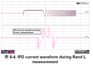
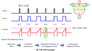
I'm confused about figure 8-4. Why is the IPD phase current value increases first in high di/dt and decrease in low di/dt ramp? Shouldn't it increase in ramp first and decay to 0 quickly? As is showed in figure 7-22?

Another question I would like to confirm is that, is the winding R measured during the rising edge in figure 8-4 and L measured during the ramp down using equation 'u=Ldi/dt'?

Many thanks!

  • Hi Joyce,

    The figure 8-4 waveform is likely captured with the IPD release mode set to Brake instead of Tri-state. Please refer to section 2.1.2 of the MCF8316A - Design Challenges and Solutions app note for more details.

    I believe that both the rise time and fall time of the phase current are taken into account when calculating R and L.

    Regards,
    Eric C.

  • Hi Joyce,

    Just some additional clarification:

    While both rise time and fall time are used to solve for R and L, the rise time depends predominantly on the L, and the R impacts the fall time more than the rise time. So it can be said that R is determined more by the fall time and L is determined more by the rise time.

    Regards,
    Eric C.