This thread has been locked.

If you have a related question, please click the "Ask a related question" button in the top right corner. The newly created question will be automatically linked to this question.

DRV8706-Q1: DRV8701S-Q1

Part Number: DRV8706-Q1

Dear E2E Team,
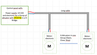
my question is about the H-Bridge driver DRV8701S-Q1. We need a control where one low-side MOSFET is driven while the other 3 MOSFETS of the H-Bridge are switched to high impedance. For our control panels we need this state for line monitoring.
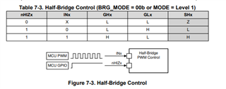
In the data sheet drv8701-q1.pdf on page 22 chapter 7.3.3.3 Split HS and Solenoid Control a mode is described where I can imagine that the control works.

According to the table I would use the following states:


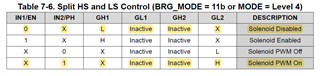
Thus the high-side MOSFET GH1 has a high impedance and the low-side MOSFET GL2 has a low impedance (switched on).
Question: What does the status Inactive mean for GL1 and GH2? What happens to the MOSFETS connected in an H-bridge to GL1 and GH2?

Best regards
Frank Mueller

  • Hi Frank,

    The best solution in this case is to use half-bridge control. Both FETs of single h-bridge can be set Hi-Z by setting nHIZx=0. For the active half-bridge, nHIZx=1 & INx=0 will enable the LOW side FET and disable the high-side FET. See the control logic table below.

    Regards,

    Pablo Armet

  • Moin Pablo,
    thank you very much for your help. I wish I had read the data sheet correctly. It is so simple ......Upside down

  • Hi Pablo,

    Can you please help us again with a second question about the DRV8706S?

    we want to control the H-bridge in a running direction (open, close) via the SPI registers. Is it possible in these states to switch the H-bridge completely to high impedance state and back again via the DRVOFF-PIN with a PWM (max. 1kHz) ?

    In PWM H-Bridge mode it is not possible to switch between "Diode Freewheel Coast" and Reverse or Forward direction with only one control line. Therefore the idea described above, which requires only one PWM line.
    We need the "Diode Freeheel Coast" for a soft start.
    PS: We do not connect a DC motor directly to the H-bridge, we use "window drives" with own electronic.

    Best regards,
    Frank Mueller

  • Question: What does the status Inactive mean for GL1 and GH2? What happens to the MOSFETS connected in an H-bridge to GL1 and GH2?

    In this mode, Inactive means GL1 and GH2 are hi-Z -- they are not switching when GH1 and GL2 are switching.

    What is your goal? I still don't understand what is your application. You don't drive motor or solenoid, then what do you drive using this driver? Could you describe your application and what is your goal?

    Btw, Table 7.6 and 7.3 are similar except that 7.6 has the GL1 and GH2 always in hi-Z output, because the user don't connect the FETs to these pins. They only use 2 FETs to drive the floating solenoid and so only 2 gate drivers are needed.

    Brian

  • Hy Brain,
    I am concerned with the second question about a soft start. See amount 4 of the chat.
    Ok, our goal is to develop a new Motorbridge to drive our owen aktuators and foreign aktuators. An actuator is a window drive with which the window or a skylight dome is opened or closed by an electric motor. The actuator opens or closes depending on the actuator polarity. In the stop state, the drive does not receive any power supply. The window drives have their own electronics for the DC motor.

    The window drives are connected in parallel to a 2-core cable. The input capacities of the drives can be different if different drives are combined on one line.
    If the drives are opened or closed from the stopped state, high starting currents are generated. It is an advantage if the drives can be started by a PWM-controlled soft start.
    Our Idea for the aktuator start : Drive DRV8706S over SPI in open or close direktion.
    During start-up, the DRV8706 is driven at pin DRVOFF via a PWM from the controller. The MOSFT bridge is thus switched back and forth from an active state to a high-impedance state depending on the PWM interval. Thus only one PWM line is needed. Does this idea work?

    Frank    

  • The actuator opens or closes depending on the actuator polarity. In the stop state, the drive does not receive any power supply. The window drives have their own electronics for the DC motor.

    So the window drive has 2 input signals: you need to define the signal voltage for open and close the window. example: +5v to open and -5v to close, and 0v to stop?

     It is an advantage if the drives can be started by a PWM-controlled soft start.

    First, you say the window is opened or closed depending on the 2 inputs polarity, and now you want to control by pwm. How does a PWM signal have positive and negative polarity? Why don't you post the window drive datasheet or some kind of specification? This is not a good engineering communication working on a project.

    How do you control the speed of the window motor? Can you control the motor speed and direction (close or open)  with the 2 wire cable?

    If the drives are opened or closed from the stopped state, high starting currents are generated.

    Not necessarily true. It depends on what control input for the window motor.

    The window drives are connected in parallel to a 2-core cable.

    Multiple window drives for one window or multiple windows? If multiple windows with drives connected to same 2wire cable, then how do you close one window and open the other window?

  • Hi Brian,

    Thank you for your replies as always!

    Hi Frank,

    Is it possible in these states to switch the H-bridge completely to high impedance state and back again via the DRVOFF-PIN with a PWM (max. 1kHz) ?

    The DRVOFF can be used to disable the half-bridge you plan on keeping Hi-Z. The LS FET pf the other half-bridge can be tied to GND. With this approach, the DRVOFF is the only input signal PWMing.

    In PWM H-Bridge mode it is not possible to switch between "Diode Freewheel Coast" and Reverse or Forward direction with only one control line. Therefore the idea described above, which requires only one PWM line.
    We need the "Diode Freeheel Coast" for a soft start.

    I'm confused here. The solution I proposed was to use the half-bridge control NOT PWM h-bridge mode. You can achieve Diode Freewheel Coast with half-bridge control using the control table in my previous reply.

    Our Idea for the aktuator start : Drive DRV8706S over SPI in open or close direktion.
    During start-up, the DRV8706 is driven at pin DRVOFF via a PWM from the controller. The MOSFT bridge is thus switched back and forth from an active state to a high-impedance state depending on the PWM interval. Thus only one PWM line is needed. Does this idea work?

    The idea is plausible. My main concern with going to a high-impedance state is that during this state, any energy stored in the motor will flow back to the power supply through the body diodes of the MOSFET and can potentially cause overvoltage at the supply pin of the DRV. Another concern is the load on the motor causing the motor to start behaving as a generator when output is high-z causing overvoltage condition. A common protection method is to add a clamping diode at the supply pin. 

    Regards,

    Pablo Armet

  • Hi Pablo,
    thank you very much for your statements. Your last statement generally answers my question about my Softstart. Furthermore, I understand our general problems of understanding. I'll try to describe it better.

    We are a manufacturer of natural smoke and heat exhaust ventilation systems. The systems consist of the actuators for opening the smoke dampers, as well as control centers for detecting alarms and the control and supply of the smoke dampers.

    The system voltage is 24VDC = supply voltage of the actuators.

    We have 3 states: OPEN, CLOSED, STOP.

    • In the STOP state we need the control of a LS-MOSFET. This is achieved by the half bridge mode of the DRV8706.
    • In the OPEN or CLOSE state we want to have a possibility to reduce high starting currents by a PWM control. The mode of the DRV is now set to full bridge mode and switched alternately to high impedance by a PWM at the DRVOFF inputpin.

    (see simplified diagram)

    best Regards,
    Frank

  • If the drives are opened or closed from the stopped state, high starting currents are generated. It is an advantage if the drives can be started by a PWM-controlled soft start.
    Our Idea for the aktuator start : Drive DRV8706S over SPI in open or close direktion.
    During start-up, the DRV8706 is driven at pin DRVOFF via a PWM from the controller. The MOSFT bridge is thus switched back and forth from an active state to a high-impedance state depending on the PWM interval. Thus only one PWM line is needed. Does this idea work?

    Hi Frank,

    With only one PWM is needed to control the window motor, how do you change the motor direction? 

    Assuming you're using SPI and 2 inputs to control the full H-bridge (either PH/EN or PWM/PWM mode), I don't see why you cannot start moving the motor from stopped state with low pwm for low current (not high starting current as you thought), then slowly increase the pwm higher to run the motor. Why do you need to have the H-bridge out puts at hi-Z during PWM off time? Example: during pwm=high, GH1=H and GL2=H and window are opening, and when pwm=L during the cycle, GL1=GL2=H to circulate the motor current, what is wrong with this as compared to having hi-Z with the diodes conducting?

    In the STOP state we need the control of a LS-MOSFET. This is achieved by the half bridge mode of the DRV8706.

    Why do you need to use half bridge during STOP state? If you use full H-bridge the with PWM=0, the 2-wire cable will have 0V and this should stop the motor.

    Brian

  • Hallo Brain,

    • the aktuator direktion is depending from the polarity of the aktuator supply voltage. This is the reason why we need an H-bridge.
    • In the main application of the DRV8706, DC motors with their motor windings are connected directly to the MOSFET bridge via the shortest possible path. For this reason, the DRV is designed in such a way that, in the case of PWM control, the motor windings short-circuit either the high-side MOSFETS or the low-side MOSFETS short-circuit the motor windings depending on the PWM.

      However, we have a long cable between the MOSFET bridge in the control panel and the drive electronics of the actuator. The drive electronics of the actuator have capacitors (up to 10µF) between the two drive lines. --> If now our H-Bridge short circuits the motor lines by the PWM controls, our input capacitors are discharged.
      So that exactly this does not happen, the H-Bridge should switch to the high-impedance state.

    • In the stop state we need the control of a LS-MOSFETT for the line monitoring up to the last actuator. For this we have a solution where we need exactly this state of the H-Bridge.

      I hope you can follow me and understand my approach.
      Have a nice weekend
      many greetings
      Frank


  • the aktuator direktion is depending from the polarity of the aktuator supply voltage. This is the reason why we need an H-bridge.

    How do you change the polarity of the actuator supply voltage via the H-bridge? Of course it needs 2 input pins, not just one pwm pin. So to open or close the window, you need to change the state of 2 input pins; one pwm is not enough as SPI cannot change the H-bridge output polarity. 

    In the stop state, the drive does not receive any power supply. 
    The drive electronics of the actuator have capacitors (up to 10µF) between the two drive lines. --> If now our H-Bridge short circuits the motor lines by the PWM controls, our input capacitors are discharged.

    It's bad to have pwm output from the DRV directly drive a 10uF cap, even through the long cable -- how long?  If the cable is long enough for a large stray inductive on the cable that you can drive the cap with PWM (VDRAIN to 0v switching), then the cap is ok to be discharged with GL1=GL2=H. If I were you I would add an inductor each to each output of the H-bridge before the 10uF to form the LC filter, then the LC circuit with synchronous switching FETs (not hi-Z when pwm=L) form a Buck DC/DC regulator with the top and bottom FETs are switching synchronously, instead of using the body diode (advance buck regulator uses sync FETs instead of one high side FET and one diode to drive the inductor). Remember that in the buck regulator, the output cap is 10x bigger than your 10uF cap and it is fine.

    If you agree with me so far, then no need to use the DRVOFF pin for the trick; just use the normal full H-bridge in PH/EN mode with gpio to drive the PH (direction) and pwm to drive the EN pin. For soft start from stop, drive pwm from low duty and increase to high duty. After actuator stopped with pwm=0 in full H-bridge, you can switch to half bridge with either GL1 or GL2 = H and the other gates =L for line monitoring as you wish.

    The idle of driving DRVOFF with 1khz will work (with PH =H and EN depends on open/close direction), but we don't know the timing spec of this DRVOFF pin and the switching speed. Also the 1khz switching with ripple voltage at the actuator might cause audible noise at this low frequency. 

    Brian