This thread has been locked.

If you have a related question, please click the "Ask a related question" button in the top right corner. The newly created question will be automatically linked to this question.

DRV8889-Q1: Connection of AOUT1 and AOUT2, BOUT1 and BOUT2 to a two-phase stepping motor

Part Number: DRV8889-Q1

hi :

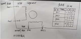
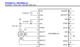
 We use DRV8889 to drive a bipolar stepper motor(See attached picture), The PIN2 of the stepper motor is connected to AOUT2, and PIN4 connected to AOUT1; PIN3 connected to BOUT1, PIN5 connected to BOUT2;The full step drive timing of this stepper motor is shown in the attached image.
1、Can this signal connection drive the stepper motor?
2、If the current flow direction AOUT1 → AOUT2 is defined as+, does it have to be BOUT1 → BOUT2 as+?      


  • Ansel,

    For #2, the answer is yes.  Please see the diagram below from our datasheet.  I think your APHASE connection is flipped.

    Regards,

    Ryan

  • HI  

       This stepper motor drive step sequence is shown in the picture A → B → C → D, which means that the DRV8889 needs to support each of the four timing sequences:
    Step A: Phase A current flows to PIN4 → PIN2, and Phase B current flows to PIN5 → PIN3;
    Step B: Phase A current flows to PIN2 → PIN4, and Phase B current flows to PIN5 → PIN3;
    Step C: Phase A current flows to PIN2 → PIN4, and Phase B current flows to PIN3 → PIN5;
    Step D: Phase A current flows to PIN4 → PIN2, and Phase B current flows to PIN3 → PIN5;
    Can the current flow direction of each phase of DRV8889 be independently set and changed? Otherwise, how can we achieve these four steps of control?

  • Ansel,

    The DRV8889-Q1 has a built in indexer that automatically controls the current direction using a simple STEP/DIR interface.  Just pulse the STEP input and it will move to the next step.  

    Please obtain an EVM and try for yourself.  It will work.

    Regards,

    Ryan