This thread has been locked.

If you have a related question, please click the "Ask a related question" button in the top right corner. The newly created question will be automatically linked to this question.

Overcurrent detection level with power ferrite beads and DRV8412

Other Parts Discussed in Thread: DRV8412

Hi,

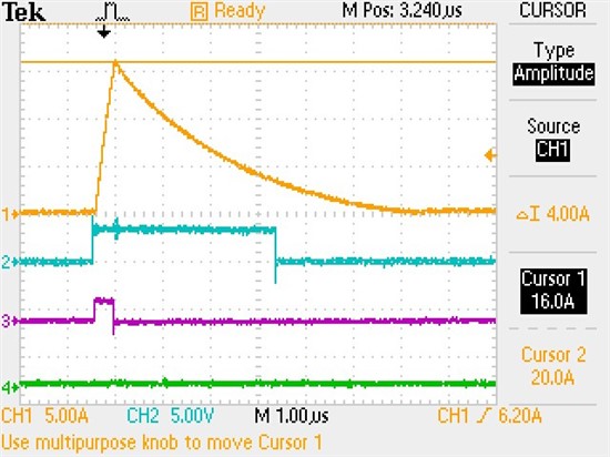
In DRV8412 datasheet it states that OC current threshold can be set by resistor values according to table 2. I guess it is assumed that inductors are placed in series with MOSFETs outputs, right? I did some OC testing on the eval board with inductors replaced by the recommended power ferrite beads. My measurement shows that the OC threshold is as high as 12A even with default 47K resistor.  I guess with power ferrite beads the chip must be used in OC latching mode since OC threshold cannot be set lower. can anyone advise on this? can anyone share more data with power ferrite beads? thanks.

Best regards

Gordon

  • Gordon,


    Something does not seem right with your measurements.  There is a 20% tolerance in expected current trip points from the values given in table 2, but I would not expect you to see currents as high as 12A with the 47k resistor used on the OC_ADJ terminal.  What mode do you have the device in?  Place it in a latching mode and observe the /FAULT pin to determine at what current the device goes into protection.  

    Please check the current ratings on the beads you have chosen.  If the beads saturate due to excessive current, they essentially become shorts and are no longer effective. I am not sure I understand what you mean about not being able to set the current lower as you can place up to a 200k resistor on the OC_ADJ pin if you wish.  


  • Hi Ryan,

    thanks for the reply.

    the test was performed in latching mode with one of the output shorting to ground directly (of course ferrite beads are in series). later i figured that 47K set the tripping point to 5.8A. however, the OC circuit takes around 250ns to react and disable the output. During this 250ns the current keeps rising and reaches 16A peak. is my understanding correct? please see below capture. when short ciruit occurs the fault LED did light up and the chip survived the test.

    i also tried 150K resistor to set the tripping point lower. i did see the peak current also reduced, which makes sense to me. please comment. thanks.

    orange: output current   blue: logic input   pink: output votlage

  • Gordon,

    Very nice.  Yes, your understanding is perfectly correct including the 250ns response time of the OC detect.