This thread has been locked.

If you have a related question, please click the "Ask a related question" button in the top right corner. The newly created question will be automatically linked to this question.

DRV8343-Q1: Reverse Supply Protection Confirmation

Part Number: DRV8343-Q1

Hi Experts,

DRV8343S-Q1 is under evaluation on customer side. The application is One-Box.

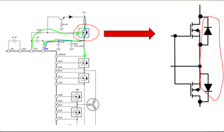
In the datasheet, it shows that the charger pump can be used for Reverse Supply Protection, see the screenshot below:

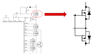
Customer want tot change the MOSFET(marked by red circuit) to 2 MOSFET, like the screenshot below, are there any risk for this kind of design? Could you check it for customer? Thanks.

Best Regards

Songzhen Guo

  • Hi Songzhen,

    The customer's proposed 2 MOSFET configuration will not work due to the back-to-back diodes preventing current flow. To use the charge pump to drive the reverse supply protection, it is necessary to allow current to flow initially through the body diode of the MOSFET to provide the needed power to the driver to be able to power up the device and enable the charge pump.

    This is illustrated in the image below: Initially, when VBAT is first applied, current flows as shown in the blue arrow through the body diode of the reverse protection MOSFET, providing sufficient voltage to turn the device on. Once the device is on and the charge pump is operational, then the charge pump will be used to actively turn on the reverse protection MOSFET, shown in the green arrow. 


    With the customer's proposed solution, current would be unable to flow through the body diodes of the reverse protection MOSFETs, which would prohibit the device from being able to turn on when VBAT is applied since the diodes would block the flow of current. This would cause the charge pump to not turn on and as a result the reverse protection MOSFETs would not be able to be turned on.

    Regards,

    Anthony Lodi

  • Thanks you so much for you r support.