Other Parts Discussed in Thread: DRV8320
We are using DRV8320RH for our motor-driver circuit.
I want to know 1) the implemented method of IDRIVE at DRV8320RH,
and 2) IDRIVE behavior when we apply software dead-time between INHx and INLx.
1) the implemented method of IDRIVE at DRV8320RH
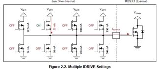
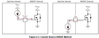
According to the technical document(Understanding smart gate drive,slva714d),
there are 2 kinds of implemented method of IDRIVE such as multiple switches, current source.
What is implemented method of IDRIVE at DRV8320RH? multiple switches or current source.
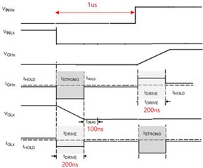
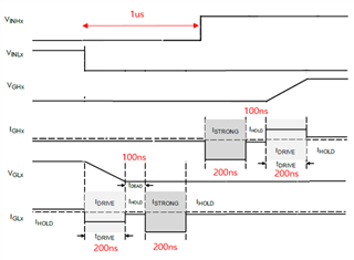
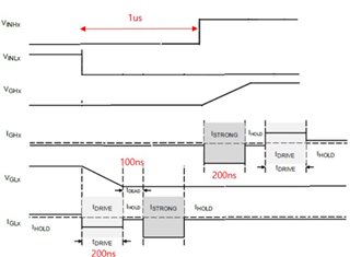
2) IDRIVE behavior when we apply software dead-time between INHx and INLx
If we apply software dead-time(1us) from MCU ( so, INLx turn-off and INHx turn-on is not switched at the same time),
what is the IDRIVE behavior? case1 of case2?
① case1
② case2