This thread has been locked.

If you have a related question, please click the "Ask a related question" button in the top right corner. The newly created question will be automatically linked to this question.

DRV8210: GND does not affect the circuit

Part Number: DRV8210

This is Youssef Elbadri from the research and development department (I-D Tech) of Nile University, one of the leading universities in engineering in Egypt and the MENA region (See our website: www.nu.edu.eg/home-page).

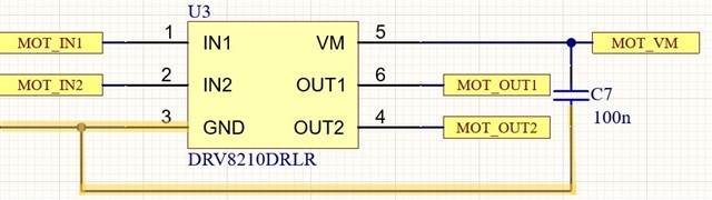
We are currently working on a project that includes a motor driver, as a result, we consider using your solution (DRV8210). We developed the application circuit as shown in the attached figure, but we have a concern regarding the GND.

Our setup is to connect the IN1 to GND, IN2 to 3.3V, VM to 6V, and GND. We expect that when we disconnect the GND pin (Making it float as illustrated in the figure), the motor stops. However, in the actual implementation, when we disconnect the GND the motor is still running in a specific direction. So, do you have any explanation regarding this behavior?

Kind Regards,
Youssef Elbadri

  • Hi Youssef,

    Our setup is to connect the IN1 to GND, IN2 to 3.3V, VM to 6V, and GND. We expect that when we disconnect the GND pin (Making it float as illustrated in the figure), the motor stops. However, in the actual implementation, when we disconnect the GND the motor is still running in a specific direction. So, do you have any explanation regarding this behavior?

    losing the GND from pin 3 will disconnect the GND from the IC circuitry. The devices should have stopped functioning and the motor stopped. The motor may continue to spins for some time after loosing GND due to the slow current decay in inductors. My theory is that there might be another path for the GND to connect to the IC. Can you measure the resistance between pin 3 and common GND of your PCB. 

    Regards,

    Pablo Armet

  • Hello Pablo,
    Thank you for your support,

    I measured the resistance, and the result is when connecting pin 3 to GND the resistance = 0ohm, and then disconnecting it the resistance = infinity.
    Is connecting IN1 to the GND effect on pin 3? as I connected IN1 to GND for all the tests.

    Kind regards,
    Youssef Elbadri

  • Youssef,

    If IN1 comes from the MCU GPIO, the DRV GND (pin 3) will be tied to the MCU GND. However, the VM supply will be open. Is the MCU GND and VM GND tied together in the PCB or are they independent?

    Regards,

    Pablo Armet

  • Our setup is to connect the IN1 to GND, IN2 to 3.3V, VM to 6V, and GND. We expect that when we disconnect the GND pin (Making it float as illustrated in the figure), the motor stops. However, in the actual implementation, when we disconnect the GND the motor is still running in a specific direction. So, do you have any explanation regarding this behavior?

    Hi,

    INx have internal pull down, so no need to connect IN1 to GND externally to simplify the ground path.

    I don't expect there is a MCU needed to control the 8210 in this test as IN1=0 and IN2=1 in the setup.

    You said "when we disconnected the GND pin", exactly how this was done? If pin3 GND is cut off from ground then there is no current flow from the 6v supply (supply GND is connected to driver pin3), so it's impossible for the motor to continue to run.

    Do this: as the motor running with the GND pin disconnected, measure the voltage from pin3 to supply GND -- it should be 6v and not 0v. 

    Brian

  • Pablo,

    I am actually supplying the IN1 GND from the same VM Supply GND.

    Kind regards, 
    Youssef Elbadri

  • Hello Brian, 
    Thank you for your help, 

    After I disconnect the ground, I measure the voltage difference between the main circuit ground and pin 3. It is niether 0V nor 6V, it is 1.6V. In addition, I measure between pin 4, 5 (Motor Outputs), and the voltage difference is 4.4V. 

    Best regards, 
    Youssef Elbadri

  • Brian,

    Thanks for your input. I always appreciated your support in the E2E forum.

    Youssef,

    After I disconnect the ground, I measure the voltage difference between the main circuit ground and pin 3. It is niether 0V nor 6V, it is 1.6V

    Interesting. There is an internal leakage path from OUTx to IC GND (pin 3). The 1.6V is most likely coming from this internal path (this path is used to short gate of MOSFET to prevent accidentally turning ON the FET). 

    I should've asked earlier but is disconnecting GND in your system a concern for you? 

    Regards,

    Pablo Armet

  • After I disconnect the ground, I measure the voltage difference between the main circuit ground and pin 3. It is niether 0V nor 6V, it is 1.6V. In addition, I measure between pin 4, 5 (Motor Outputs), and the voltage difference is 4.4V. 

    Hi,

    This makes no sense at all.

    1. With pin3 not connected, there is no current path from VM to GND (6v return). Do you still have an external pull down resistor on IN1 or let the internal pull down to hold it low? Without the external pull down resistor, pin3 should be 6v as there is zero current flow from VM to pin3.

    2. 

    You said "when we disconnected the GND pin", exactly how this was done? If pin3 GND is cut off from ground then there is no current flow from the 6v supply (supply GND is connected to driver pin3), so it's impossible for the motor to continue to run.

    Why not try to answer this question?