Other Parts Discussed in Thread: CSD18532Q5B,
Hello TI Team,
We are facing a problem in mosfet that we selected.
Few years ago we had purchased a mosfet which was on an evalutation board we purchased locally. It had Mosfet NCE40H12K. (D2PAK)
This worked really well for us and we faced no issues.
Due to pandemic and shortage in market of components we decided to buy this mosfet from same vendor but this time this batch was not functioning as we expected.
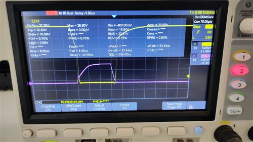
The pulses on Gate was noticed but the driver was unable to run the motor. We had no idea what was the difference in pulses. It was difficult for us to identify which parameter could had been different here.
We choose another mosfet with similar specifications and that worked. SQR50N04-3m8 We got few samples of these and tested and worked well. One big problem with this was it is Reverse mounted. And our pcb was not meant for it. But we used it for emergency backup during production.
The ti evaluation board uses another mosfet CSD18532Q5B which is also different package and not suitable for us as some of them are already in field and we want to maintain the stock.
Our motor specifications
Motor voltage: 24V
Motor current max: 6A (peak during friction in mechanism), 3A (continuous for 5seconds)
Stall condition: Motor is disabled upon 1second stall at peak current.
Questions:
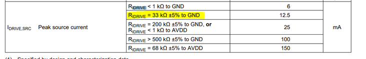
1. What is the specification to look at when we are selecting the mosfet for DRV8701?
2. I've made comparison chart between mosfets I discussed on top. Most specifications are similar but td(on) and td(off) and rise and fall are different. Does these parameters matter? If so as per question 1, if some reference guide for this selection that will help.
| param | New selected SQR50N04-3m8 | Tested for year NCE40H12K | Ti eval CSD18532Q5B |
| Type | Nch Mosfet | Nch Mosfet | N CH PWR mosfet |
| VDS(v) | 40 | 40 | 60 |
| RDS(on) at Vgs 10V | 0.0038 | 0.0036 ~ 0.004 | 0.0033~0.0043 |
| ID (A) | 50 | 120 | 172 |
| Package | TO-252 rev | TO-252 | 8-VSONP |
| Vgs(th) (v) | 2.5~3.5 | 1.2 ~ 2.5 | 1.5 ~ 2.2 |
| td(on) ns | 11 ~ 16 | 15 | 5.8 |
| td(off) ns | 34 ~ 51 | 52 | 22 |
| rise time ns | 5 ~ 8 | 18 | 7.2 |
| fall time ns | 9 ~ 14 | 23 | 3.1 |
| pulsed current A | 200 | 120 | 400 |
| forward V VsD | 0.9 ~ 1.5 | 1.2 | 0.8 ~ 1 |
3. Based on CSD18532Q5B mosfet specifications, I was browsing on digikey and found similar mosfet which looks quite promising as well but until I know what parameters to look at we will be in doubt.
https://www.digikey.in/en/products/detail/infineon-technologies/IRFS7530TRLPBF/4772499
Best regards,
Macjan