


Other Parts Discussed in Thread: MCF8315A,
Abstract
Sensorless Brushless DC (BLDC) motors are widely used in industrial and medical applications such as vacuum cleaners, pumps, CPAP blowers etc. Decelerating a BLDC motor in these applications is one of the key requirements. Fast deceleration can be very challenging in BLDC motors as the motor kinetic energy can kick back into the motor driver system and cause voltage overshoot in power supply. Another challenge in fast deceleration is that the BLDC motor can lose synchronization at lower speeds. This article describes how the active braking feature in MCF8316A and MCF8315A can overcome these challenges to provide a faster and safer motor deceleration.
BLDC motor electrical model
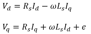
Basic electrical model of BLDC motor or Permanent magnet synchronous motor (PMSM) in d-q axis is shown in Figure 1.
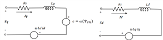
Figure 1. BLDC Motor Electrical model
BLDC motor in motoring mode
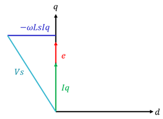
Figure 2. Phasor diagram of BLDC motor in motoring mode
- Considering the motor to be Surface mount permanent magnet synchronous motor (SMPMSM), phase current on d-axis (Id) is 0.
- Phasor diagram in Figure 2 shows the motor in motoring mode. In this mode, the Motor driver drives the motor to generate mechanical energy. Phase current in q-axis that generates the motor torque is in alignment with the Back EMF (BEMF) voltage to generate maximum torque.
- In motoring mode, the input electrical power Pin = Vd*Id + Vq*Iq . Since Id = 0, Pin = Vq*Iq or e*Iq where e is the BEMF voltage and Iq is the phase current in q-axis. Output mechanical power generated by the motor is Pout = T*ω where T is the torque and ω is the motor speed.
- Ignoring the motor losses and resistance drop across Rs, torque generated by the motor, T = e*Iq/ω.
BLDC motor in normal braking mode
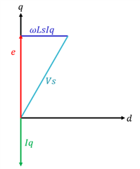
Figure 3. Phasor diagram of BLDC motor in normal braking mode
- In normal braking mode, negative torque is applied to brake the motor, so the phase current Iq and torque T will be negative.
T = -e*Iq/ω
- Phasor diagram in Figure 3 shows the motor in normal braking mode. In this mode, phase current is out of phase with BEMF voltage to brake the motor.
- In this mode, the input electrical power Pin = -e*Iq which means the power will flow into the motor driver causing the DC bus voltage to overshoot.
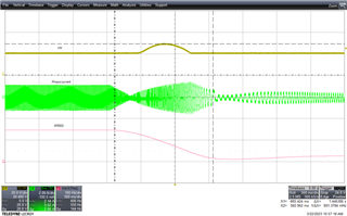
Figure 4. DC bus voltage, phase current and motor speed in normal braking mode
Figure 4 shows the DC bus voltage in Yellow, phase current in Green and Motor speed in pink. In normal braking mode, when the motor decelerates from 100% speed to 20% speed, DC bus voltage overshoots from nominal voltage of 20V to 28.8V. Time taken for the motor to decelerate from 100% to 20% speed is 1.45 seconds.
BLDC motor in Active braking mode
Decelerating the motor quickly requires motor mechanical energy to be extracted and disposed - input DC voltage increases if this energy is returned to the DC input supply. When active braking is enabled, energy taken from DC power supply is used to brake the motor - this prevents DC voltage spike during fast deceleration. The mechanical energy of the motor and energy taken from DC source, both are dissipated within the motor itself.
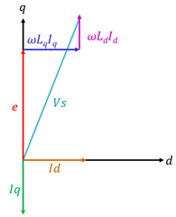
Figure 5. Phasor diagram of BLDC motor in active braking mode
Phasor diagram in Figure 5 shows the motor in active braking mode. In this mode, positive Id current is injected into the motor such that the Vd*Id component in is greater than Vq*Iq. Since Pin is greater than zero, power will not flow back into the DC power supply.
In MCF8316A and MCF8315A, ACTIVE_BRAKE_EN should be set to 1b to enable active braking and avoid DC bus voltage spike during fast motor deceleration. Active braking can also be used during reverse drive or motor stop to reduce the motor speed quickly without DC voltage spike. The maximum limit on the current sourced from the DC bus (idc_ref) during active braking can be configured using ACTIVE_BRAKE_CURRENT_LIMIT. The power flow control during active braking is achieved by using both Q-axis (iq) and D-axis (id) components of current. The D-axis current reference (id_ref) is generated from the error between DC bus current limit (idc_ref) and the estimated DC bus current (idc) using a PI controller. The idc value is estimated from the measured phase currents, phase voltage and DC bus voltage, using power balance equation (equating the instantaneous DC bus power to sum of all three instantaneous phase power assuming 100% efficiency). During active braking, the DC bus current limit (idc_ref) starts from zero and linearly increases to ACTIVE_BRAKE_CURRENT_LIMIT with current slew rate as defined by ACTIVE_BRAKE_BUS_CURRENT_SLEW_RATE. The gain constants of PI controller can be configured using ACTIVE_BRAKE_KP and ACTIVE_BRAKE_KI. Figure 6 shows the active braking id current control loop.

Figure 6. shows the active braking id current control loop
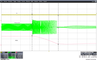
Figure 7. DC bus voltage, phase current and motor speed in active braking mode
Figure 7 shows the DC bus voltage in Yellow, phase current in Green and Motor speed in pink. In active braking mode, when the motor decelerates from 100% speed to 20% speed, DC bus voltage does not overshoot. Time taken for the motor to decelerate from 100% to 20% speed is 1.38 seconds.
Conclusion
Waveforms in Figure 4 and Figure 7 show how TI’s Active braking feature can decelerate the motor quickly without overshooting the DC bus voltage. For more details, please check below links.
MCF8316A - www.ti.com/product/MCF8316A
MCF8315A - www.ti.com/product/MCF8315A
