


Other Parts Discussed in Thread: LAUNCHCC3235MOD,
Good evening Texas Instruments!
I am currently attempting to control the DRV8462EVM via SPI using the LAUNCHCC3235MOD as the master device. I am having trouble getting the motor to take any steps, and I was wondering if anybody could point me in the right direction. I've used these sorts of drivers before, but strictly in a H/W setup rather than SPI. I'm sure I'm just missing something painfully obvious.
I am attempting to send two uint16_t values over SPI to addresses 0x04 and 0x05 (0b0000010010001111 and 0b0000010111110000). I'm not trying to do anything too complex, I'm just trying to instruct the motor driver to take steps. Does anything pop out as obviously incomplete or incorrect?
The motor is holding its position and buzzing.
Below, I have attached my code. I'm using FreeRTOS!
#include <stdint.h>
#include <stddef.h>
#include <stdbool.h>
#include <string.h>
#include <ti/drivers/GPIO.h>
#include <ti/drivers/Timer.h>
#include <ti/drivers/UART2.h>
#include <ti/drivers/SPI.h>
#include <pthread.h>
// #include <semaphore.h> // May not use semaphores this time.
#include <unistd.h>
#include "ti_drivers_config.h"

// TMP global uart define:
static UART2_Handle uart;

// TMP global led pin defines:
const uint8_t led_red = 10;
const uint8_t led_green = 11;
const uint8_t led_blue = 9;

void *masterThread(void* arg0)
{
  SPI_Handle      masterSpi;
  SPI_Params      spiParams;
  SPI_Transaction transaction;
  bool            transferOK;

  // Outputs:
  GPIO_setConfig(CONFIG_GPIO_nSLEEP, GPIO_CFG_OUT_STD | GPIO_CFG_OUT_LOW);
  GPIO_setConfig(CONFIG_GPIO_MODE,   GPIO_CFG_OUT_STD | GPIO_CFG_OUT_LOW);
  GPIO_setConfig(CONFIG_GPIO_ENABLE, GPIO_CFG_OUT_STD | GPIO_CFG_OUT_LOW);

  // Open SPI as master (default)
  SPI_Params_init(&spiParams);
  spiParams.frameFormat = SPI_POL0_PHA0; // Need to check this. // SPI_POL0_PHA1
  spiParams.bitRate = 10000; // 10000000
  spiParams.dataSize = 16;
  masterSpi = SPI_open(CONFIG_SPI_MASTER, &spiParams);
  if (masterSpi == NULL)
  {
    while (1);
  }

  // Configure the the motor driver in SPI mode:
  GPIO_write(CONFIG_GPIO_nSLEEP, 0);
  sleep(1); // tmp
  GPIO_write(CONFIG_GPIO_MODE, 1);
  sleep(1); // tmp
  GPIO_write(CONFIG_GPIO_nSLEEP, 1);
  GPIO_write(CONFIG_GPIO_ENABLE, 1);
  UART2_write(uart, "READY\r\n", 7, NULL);
  while (1)
  {
    // Write to CTRL1 and CRTL2:
    uint16_t tx_buf[2] = {0b0000010010001111, 0b0000010111110000};
    uint16_t rx_buf[2];
    memset((void *) rx_buf, 0, 2);
    transaction.count = 2;
    transaction.txBuf = (void*) tx_buf;
    transaction.rxBuf = (void*) rx_buf;
    transferOK = SPI_transfer(masterSpi, &transaction);
    // SPI transfer:
    GPIO_write(led_red, 1);
    transferOK = SPI_transfer(masterSpi, &transaction);
    if (transferOK)
    {
      UART2_write(uart, "TC\r\n", 4, NULL); // Transfer Complete.
    }
    GPIO_write(led_red, 0);
    volatile int i;
    for (i = 0; i < 10000; i++)
    {
      // TMP "delay."
    }
  }
  SPI_close(masterSpi);
  return (NULL);
}

void timerCallback(Timer_Handle Handle, int_fast16_t status)
{
    GPIO_toggle(led_blue);
}

void *mainThread(void* arg0)
{
  // Initialization:
  GPIO_init();
  Timer_init();
  SPI_init();

  // LED Outputs:
  GPIO_setConfig(led_red,   GPIO_CFG_OUT_STD | GPIO_CFG_OUT_LOW);
  GPIO_setConfig(led_green, GPIO_CFG_OUT_STD | GPIO_CFG_OUT_LOW);
  GPIO_setConfig(led_blue,  GPIO_CFG_OUT_STD | GPIO_CFG_OUT_LOW);

  // Set initial LED states:
  GPIO_write(led_red,   1);
  GPIO_write(led_green, 1);
  GPIO_write(led_blue,  1);

  // Timer:
  Timer_Handle timer_0;
  Timer_Params timer_params;
  Timer_Params_init(&timer_params);
  timer_params.period = 1000000;
  timer_params.periodUnits = Timer_PERIOD_US;
  timer_params.timerMode = Timer_CONTINUOUS_CALLBACK;
  timer_params.timerCallback = timerCallback;
  timer_0 = Timer_open(0, &timer_params);
  if (timer_0 == NULL)
  {
    while (1); // Timer_open() failed!
  }
  if (Timer_start(timer_0) == Timer_STATUS_ERROR)
  {
    while (1); // Timer_start failed!
  }
  GPIO_write(led_red, 0); // Timer creation success.

  // UART:
  UART2_Params uart_params;
  UART2_Params_init(&uart_params);
  uart_params.baudRate = 115200;
  uart = UART2_open(CONFIG_UART2_0, &uart_params);
  if (uart == NULL)
  {
    while (1); // UART2_open failed!
  }
  GPIO_write(led_green, 0); // UART creation success.

  // SPI setup:
  pthread_t           thread0;
  pthread_attr_t      attrs;
  struct sched_param  priParam;
  int                 retc;
  int                 detachState;
  pthread_attr_init(&attrs);
  detachState = PTHREAD_CREATE_DETACHED;
  retc = pthread_attr_setdetachstate(&attrs, detachState);
  if (retc != 0)
  {
    while (1); // pthread_attr_setdetachstate() failed!
  }
  retc |= pthread_attr_setstacksize(&attrs, 2048); // TODO
  if (retc != 0)
  {
    while (1); // pthread_attr_setstacksize() failed!
  }
  priParam.sched_priority = 1;
  pthread_attr_setschedparam(&attrs, &priParam);
  retc = pthread_create(&thread0, &attrs, masterThread, NULL);
  if (retc != 0)
  {
    while (1); // pthread_create() failed!
  }
  GPIO_write(led_blue, 0); // SPI creation success.

  while (1)
  {
    UART2_write(uart, "Green\r\n", 7, NULL);
    GPIO_toggle(led_green);
    volatile int i;
    for (i = 0; i < 10000; i++)
    {
    }
  }
}
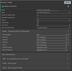
SPI configuration:
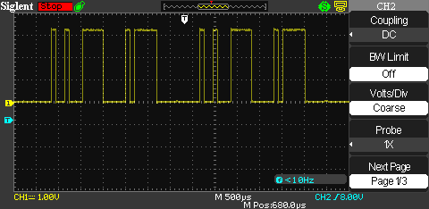
Screenshot of the data being sent over MOSI to SDI:
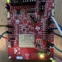
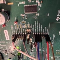
Images of my hardware setup:
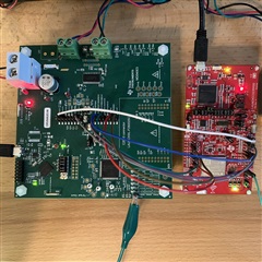
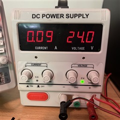
My DC power supply (while attempting to run):
Any help would be very, very appreciated. I am still new to all of this!
Thank you so much,
Dan

