This thread has been locked.

If you have a related question, please click the "Ask a related question" button in the top right corner. The newly created question will be automatically linked to this question.

ULC1001-DRV290XEVM: Piezo transducer specification

Part Number: ULC1001-DRV290XEVM
Other Parts Discussed in Thread: ULC1001

Hi 

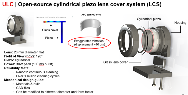
We are researching  on ULC architecture.

How to Choose the ring-shaped piezo transducer? About driving voltage, frequency range, vibration mode......

Thanks and Best Regards

Weite

  • Hi Weite, 

    I have a few links that can help answer your question. 

    1. Our piezo vendor has a piezo calculator, which can quickly estimate a few key parameters, such as resonant frequency. https://www.americanpiezo.com/knowledge-center/apc-piezo-calc.html

    2. Regarding the driving voltage directly across the piezo, typically it is 100-150V peak to peak per mm thick. 

    3. Modes of vibration for piezoelectric elements. https://www.americanpiezo.com/knowledge-center/piezo-theory/vibration.html

    Let me know if you have any questions.  

    Thanks and best regards

    Hailong 

  • Hi Hailong,

    Thanks for your reply.

    And what should be paid attention to when choosing a piezo transducer?

    How about the driving of ULC1001-DRV290XEVM?

    How to choose a piezo transducer to match ULC1001-DRV290XEVM?

    Thanks and Best Regards

    Weite 

  • Hi Weite,

    We are working on this and will get back to you ASAP.  Thanks.

    -Jeff

  • Weite, 

    For designing the lens cover ( piezo + lens), the key is designing the dimensions of piezo whose resonant frequency can match the lens. 

    For the ULC1001 device, it supports a wide range of resonant frequencies of piezo and the EVM can be calibrated to match the piezo.  

    With regarding to how to drive the ULC1001-DRV290XEVM properly, please refer to the user guide or design guide for details. 

    Let me know if you have more questions. 

    Thanks

    Hailong


  • Hi Hailong,

    Thanks for your reply.

    I have other questions to ask.

    1. How the ULC1001-DRV290XEVM detects substances(water, ice, mud...) on Lens Cover system?

    2. And how to detect temperature on Lens Cover system?

    Because the ULC1001-DRV290XEVM only used two pins(OUT_XA/OUT_XB) to LCS(Lens cover system).

    Thanks and Best Regards

    Weite

  • Hi Hailong,

    It is mentioned in the data that the Exaggerated vibration (displacement ~10 μm) of Piezo.

    Why is the Piezo vibration displacement 10um?

    And how much displacemen is the minimum and maximum? What are the limiting factors?

    Thanks and Best Regards

    Weite

  • 1. All contaminants (water, ice, mud) have weight. The weight will decrease the resonant frequency of the system. The mechanical system can be simplified as f= sqrt(k/m), where k is the spring constant and m is mass. ULC1001 can monitor the frequency shift and therefore know the substances. Therefore, the piezo can be used as an actuator and a detector. 

    2.  The ULC1001 detect temperature based on the impedance response of the mechanical system. When the piezo vibrates, and the temperature goes up and also its impedance magnitude will go up as well. Basics, temperature T= a x Impedance magnitude + b, where a is slope constant and b is a temperature constant. 

    The two pins will constantly monitor the impedance response and therefore is able to detect the mass and sense the temperature. 

  • Hi Weite,

    The piezo displacement is around 10 um during the water cleaning operation, which is the maximum. The minimum is 0 at rest.

    With higher driving voltage, the displacement will be bigger than 10um. With our current settings, the piezo displacement is at the level of 10 um. Of course, the displacement cannot keep going up with voltage. It will saturate to a certain level or even damage the piezo if driving further.   

    Let me know if you have more questions. 

    Thanks

    Hailong