Hi,
We are in the process of mass production.Sometimes in the field, there is a problem with the BDC motor not turning.
If a problem occurs, attempting reverse rotation or turning the motor ON/OFF does not solve the problem.
When power is reapplied, there are times when it operates normally, and there are times when it still does not operate.
However, if the power is applied again after a few hours, most of them operate normally.
When I checked V_DC power supply, IN1, IN2 in the problem state, everything is fine. There is only no power output on OUT1 and OUT2.
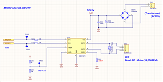
The frequency is 10KHz and the duty cycle is 16~100%.When starting, soft start is performed, and there is no load.
Motor:
DC40V, 35,000RPM, 180mA(no load)
I can't find the cause of the problem.
I need your kind advice.
I attach the circuit diagram and scope capture screen.
circuit is below
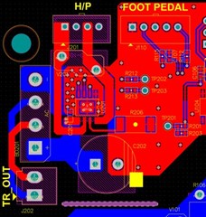
pcb artwork
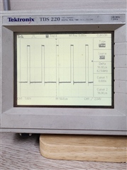
V_DC capture

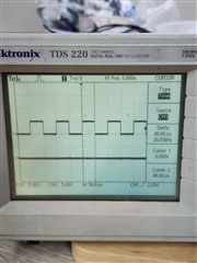
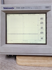
IN1 PWM

IN1 Duty cycle (16%~100%)
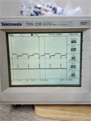
IN2 capture
VREF=4.17V