This thread has been locked.

If you have a related question, please click the "Ask a related question" button in the top right corner. The newly created question will be automatically linked to this question.

MCT8329A: Cannot communicate with MCT8329A via I2C

Part Number: MCT8329A
Other Parts Discussed in Thread: MCT8329EVM, MSP430FR2355, MCF8316AEVM

Hi team,

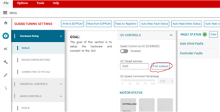
Customer is utilizing MCT8329A but cannot communicate with it at the first step.

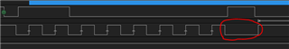
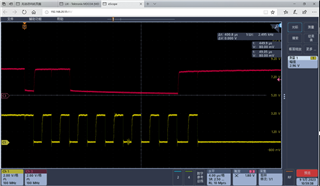
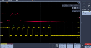
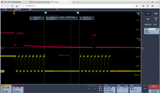
They are using the MCU board to write I2C command to MCT8329's EEPROM: Start + targetID(110 0000)+ (0), but it fails to communicate at the 9th high signal of SCL, shown as,

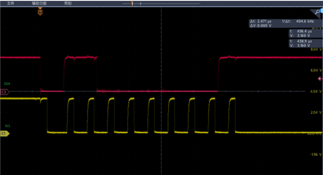
I notice there is another thread in E2E of communication issue, shown here, https://e2e.ti.com/support/motor-drivers-group/motor-drivers/f/motor-drivers-forum/1215901/mct8329evm-i-couldn-t-start-communication/4616637?tisearch=e2e-sitesearch&keymatch=MCT8329#4616637

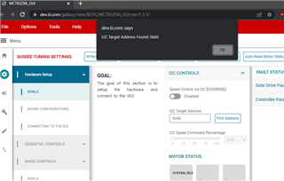
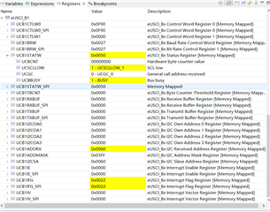
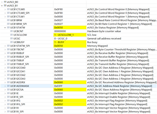
Not sure is there some address mismatch or some other issue? Pls kindly help on this.

Regards,

Xiaoying

  • Hi Xiaoying,

    Yes, it's possible that there's a mismatch between the MCT8329's I2C target address and the GUI's configured I2C target address.

    I've just published a new MCT8329A GUI. In this new version 1.1.1, I've added a "Find Address" button in the I2C Controls side panel:

    Could you please instruct the customer to run this new MCT8329A GUI version 1.1.1, connect the EVM to PC, power-up the MCT8329 via PVDD, then click on the "Find Address" button? The GUI will automatically search through all possible I2C Target Address until it finds the correct address, at which point a pup-up dialog will indicate the found Target Address:

    Regards,
    Eric C.

  • Hi Eric,

    But this error occurs in customer's own board, not the EVM. So seems that they cannot use the GUI?

    They are using other MCU board to communicate with MCT8329 directly but failed. Is there any way to find/read the right target ID? Or any other problem can cause this communication failure?

    Regards,

    Xiaoying

  • Hi Xiaoying,

    If they do have an EVM, then they could connect the SDA, SCL, and GND from the MSP430 on the EVM over to their customer board and utilize the GUI.

    If EVM is not available, and assuming incorrect I2C Target ID is the cause of the issue, then they can simply brute force and try sending I2C command with all the possible target address 0x00 ~ 0x7F (0~127) using their MCU board to find the right address.

    Lastly, I would also ask the customer to verify that the voltage regulator AVDD and DVDD outputs are nominal 3.3V and 1.5V. And make sure that the FG and nFAULT pins are pulled-up to 1.8V ~ 5V through external pull-up resistors.

    Regards,
    Eric C.

  • Hi Eric,

    Customer has tried all the I2C addresses but doesn't work.

    It is very strange that their MCU board can connect with other devices, but just cannot connect MCT8329. And they strictly followed our EVM to design the schematics. Besides the AVDD, DVCC, and FG/nFAULT pins, it there any other possible causes?

    Regards,

    Xiaoying

  • Hi Xiaoying,

    I can't think of any other possible schematic related issues that could cause the MCT8329 to not respond to I2C command.

    One thing I noticed in the waveform captured above is the MCU doesn't seem to implement clock stretching to allow the MCT8329 time to respond with ACK. Could you please ask if the customer can implement clock stretching?

    Here's an example I2C transaction of START + TargetAddr + W0 + ACK captured on the MCT8329EVM:

    Regards,
    Eric C.

  • Hi Eric,

    Thank you for your help. This question was asked by Xiaoying for me

    The latest test results are as follows

    The mcu board is MSP430FR2355 LaunchPad

    The project is “8867.HardwareI2C_MSP430FR2355_MCF8316AEVM” 

    I only changed the SLAVE_ADDR from 0x01 to 0x60, and INTER_BYTE_DELAY from 5600 to 700

    1.use MSP430FR2355 LaunchPad to communicate with MCT8329A,

    after EUSCI_B_I2C_masterSendStart(EUSCI_I2C_BASE); excuted,

    The register status is as follows

    And the waveform is as follows

    2.use MSP430FR2355 LaunchPad to communicate with F280025 LaunchPad,

    F280025 was configure as slave, and set its address 0x60


    after EUSCI_B_I2C_masterSendStart(EUSCI_I2C_BASE); excuted,

    The register status is as follows

    And the waveform is as follows

    The complete starting byte and the first data byte 0x10 waveform are as follows, and it can be seen, about 25 us delay was insert between the starting byte and its ack,


    can the results indicate the “clock stretching” has been implemented in “8867.HardwareI2C_MSP430FR2355_MCF8316AEVM” ?

    and Can this indicate that MSP430 LaunchPad has already worked as 8329a expected ?


    Regards

  • Hi Eric,

    1.we have check the  AVDD and DVDD outputs are nominal 3.3V and 1.5V.  And the FG and nFAULT pins are pulled-up to 3.3V through external 5.1k resistors, but an optocoupler is connected to FG  and nFAULT pins respectively in our pcb,in this condition, the voltage of FG and nFAULT pin is about 1.1 V, will this affect the I2C communication of MCT8329A?

    2.The connection pins between MSP430FR2355  LaunchPad with MCT8329A are only GND,SCL, and SDA. 

    3.As to "clock stretching", I know little about it, I have review the MSP430FR4xx and MSP430FR2xx family User's Guide,I only find "The UCSCLLOW bit can be used to observe if another device pulls SCL low while the eUSCI_B modulealready released SCL". So if the “8867.HardwareI2C_MSP430FR2355_MCF8316AEVM”  for  MSP430FR2355 LaunchPad didn"t implement clock stretching, could you please give me some instruction about  implementing it with MSP430FR2355  LaunchPad?

    thank you!

    Regards,
    deming

  • Hi Eric

    after remove optocoupler  connected to FG  and nFAULT pins,  the voltage of FG and nFAULT pin recovery 3.3V , I2c can work 

    Regards,
    deming