Hi suppoert team,
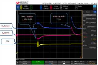
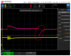
I use DRV8873H to control motor. It can detect start current when I_Start> I_Trip = 6,5 [A], it turn to pwm mode. But I see that it can not detect the break current (I_brake) althougt I_brake > Iocp. Normally it shoud detect Iocp to protect itself, is it right?
More Infos:
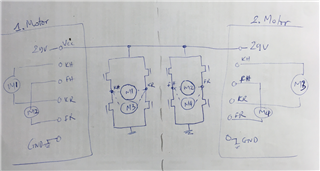
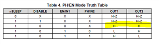
- PH/EN Mode
- brake the motor with OUT1 and Out2 = H
Thank you
Best regards,
Oat