Hi team,
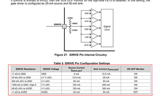
How is IDRIVE selected? According to the data sheet, it is hard to apply on many devices:


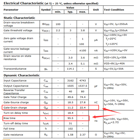
If the following MOS exceeds these values, will it not be driven?

Could you help check this case? Thanks.
Best Regards,
Cherry
This thread has been locked.
If you have a related question, please click the "Ask a related question" button in the top right corner. The newly created question will be automatically linked to this question.
Hi team,
How is IDRIVE selected? According to the data sheet, it is hard to apply on many devices:


If the following MOS exceeds these values, will it not be driven?

Could you help check this case? Thanks.
Best Regards,
Cherry
Hi,
Adding a new question:
If current sensing is used, connect SP/SN to the sampling resistor while simultaneously connecting the sampling resistor to another op amp for current data reading. In other words, a sampling resistor is used for the SP/SN pin of 8701 and also for an op amp in parallel so that the current value can be read by the monolithic.
Thanks and regards,
Cherry
Cherry,
For the first question, customer can ignore the "rise time" spec in MOS datasheet. I am not sure why that is there. The Qgd is important specification and they need to decide how quickly they want to drive the FET by using equations in the datasheet to calculate Idrive depending on desired rise/fall time they want.
For second question, why do they need an external op amp? There is a SO pin on the device that can be used to monitor current in sense resistor connected across SP/SN. Internal current regulation can still be used and SO pin voltage can be read by external MCU. I don't see the need for external op amp.
Regards,
Ryan
Hi Ryan,
Thanks for your support.
For the first question, customer can ignore the "rise time" spec in MOS datasheet. I am not sure why that is there. The Qgd is important specification and they need to decide how quickly they want to drive the FET by using equations in the datasheet to calculate Idrive depending on desired rise/fall time they want.
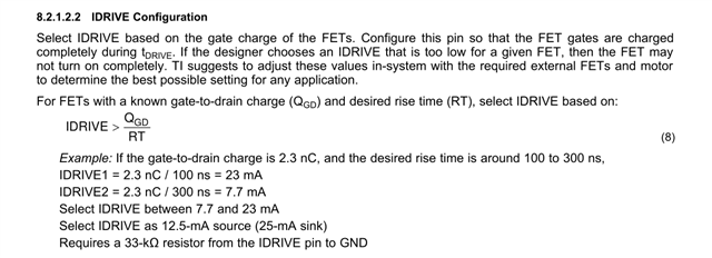
What exactly is this calculation here? What exactly does the drive current flow for IDRIVE get? Could you help give an example?
For second question, why do they need an external op amp? There is a SO pin on the device that can be used to monitor current in sense resistor connected across SP/SN. Internal current regulation can still be used and SO pin voltage can be read by external MCU. I don't see the need for external op amp.
What is the voltage at the SO output? According to the manual, 20 at AV, then if the sampling resistance is 0.01 Ω, the current is 10A, the input voltage is 0.1V, the SO output voltage is 0.1V*20=2V, and the MCU reading is 2V, is that right?
Thanks and regards,
Cherry
Cherry,
An example calculation is given in the first post on this chain. Section 8.2.1.2.2 of the datasheet. There shouldn't be any confusion. Customer should know desired slew rate and calculate Idrive based on their FET.
Please see this section in the datasheet for SO calculation. Equation 2.
7.3.4 Amplifier Output SO
Voff is typically 50mV. This offset needs to be added to the output per the equation.
Regards,
Ryan