This thread has been locked.

If you have a related question, please click the "Ask a related question" button in the top right corner. The newly created question will be automatically linked to this question.

What PN should be suitable for motor current control (inline current sensing)?

Other Parts Discussed in Thread: DRV8353, INA225, INA240

Hello,

Check the H-bridge schematic bellow:
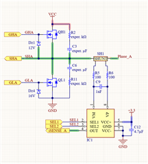
I'm going to use inline current sensing method to control a BLDC motor, using the DRV8353 driver.
So I need a suggestion for a suitable current sensor which capabilities are related to:

- Vcm >= 60V (desirable)
- Bidiretional (needed)
- Zero-Drift (desirable)
- Programmable-Gain
- Bandwidth for max gain > 100kHz (needed)

Note that.: I need a resolution of current not lower than 10mA DC for the max gain, so for a 12bit uC, I will ideally need a max gain of more than 100 considering a 1mOhms shunt resistor (consider also the max value for the shunt resistor is 2.5mOhm). For the min gain, a 12bit uC must measure a max current of at least 80A DC.
 

A nearly good solution is to use an INA225, but its Vcm is way lower than expected and I also don't know if this chip can handle a mA range. So, please anwer the questions:

1. Could you please indicate other products that fit in the specifications above?
2. Can you show the analysis you do to garantee the selected chip is capable of measuring a 10mA current? (show the analysis for the INA225)
3. In the iten above, please indicate the parameters in the datasheet that make possible to measure the 1mA range.

  • Hi,

    Here are the answers to your questions:

    1. We don’t have a device that fits all five requirements. If “Programmable-Gain” is not a must-have, then INA240 and INA241 can be used.
    2. Since INA240/241 measures input differential voltage directly, not current, the value of shunt resistor has to be taken into consideration in order to evaluate whether the system is capable of measuring a 10mA current. Please check out the error calculator tool offered by TI, you’ll find it very helpful in evaluating system accuracy. Here is the link to download.
    3. Same as 2 above.

    Regards, Guang  

  • hello,
    Thank you for the explanation, but I still have some questions.
    Considering for example the INA240 with Gain=50, which have max Vos(Offset voltage, input-referred) of +/-25uV.
    Considering using a 2mOhm shunt resistor:

    1. Is it right to say that a 1mA current would be sensed as ( 1mA  * 2mOhm  + 25uV )* 50 = 1.35mV ? If so, is it possible to eliminate this behave by a software offset (calibration)?
      
    2. What would be the best mA resolution for the INA240, considering this and other effects ?

  • Hi,

    1. Considering offset could be positive/negative, the output (signal + offset) would be in the range of (1mA  * 2mOhm  ± 25uV )* 50 = -1.15mV and 1.35mV. For current smaller than 12.5mA, the output is dominated by offset and the signal is masked. We should also be mindful of the output linear range if we're talking about minimum measurable current.
    2. Resolution is different from minimum measurable current. Since INA240 is an analog part that measures voltage, in theory it has infinite resolution. If you have an ideal voltage meter or ADC with relatively infinite resolution, or take very long measurements, you should be able to tell the difference between 20mA and 21mA. In other words, you’ll be able to achieve 1mA resolution. But in reality noise and ADC resolution will have an impact besides the shunt resistor.

    Regards, Guang  

  • Hello, Guang.
    About your considerations above:
    1.1 Once the offset is measured, is it possible to perform a software calibration to get rid of this random offset value? In other words, is this offset a fixed value (considering constant temperature)?
    1.2 What parameter by datasheet tell the limit for the linear range?
     2. Considering the INA240, what will be the error calculation related to the resolution and the noise?

  • Hi,

    • Offset is a fixed value (considering constant temperature) for a specific unit. But it will be different from unit to unit. Therefore, calibration needs to be carried out for each unit.
    • The linear range typically is within the output swing limits, and the expected output should not be outside this range:

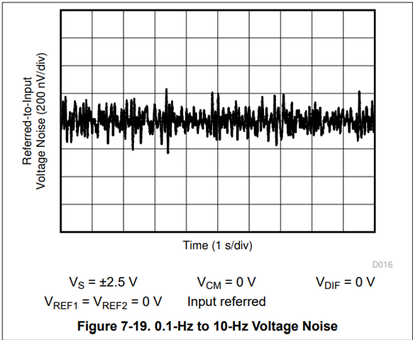
    2   Noise is specified in the datasheet. The signal to differentiate must be above the noise floor. As an example, Fig 7-19 shows input referred noise, the peak to peak noise is about 0.5uV. If system noise bandwidth is limited to 10Hz, then DC signals above this level should be detectable: 0.5uV/2mOhm = 0.25mA.  

    Regards, Guang