A related question is a question created from another question. When the related question is created, it will be automatically linked to the original question.
If you have a related question, please click the "Ask a related question" button in the top right corner. The newly created question will be automatically linked to this question.
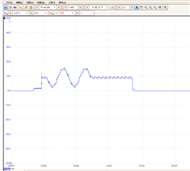
I use I2C,control waveform generator enerate sine wave,but some santooth shape is on the sine wave. How to eliminate this sawtooth wave?
What is the frequency and amplitude of the sinewave? I would think the DAC output might have big steps (sawtooth) if the frequency is low and magnitude is high.
Also, are you taking a single ended measurement? What you are likely seeing is the boost converter switching. This part is designed for only differential output, which cancels out the boost converter switching.